Hi everyone,
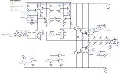
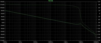
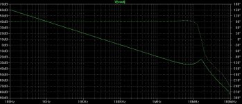
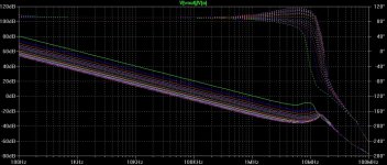
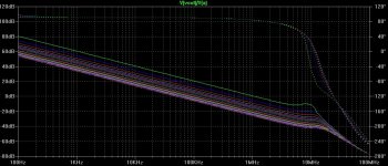
I'm testing several IPS-VAS topologies based on Bob Cordell's designs, and I've noticed that the JFET input amps seem to have more THD20, so I've replaced the JFETs with BJTs and I've removed the voltage limiter cascode transistors. When I was testing the open loop gain I've noticed that gain peaking was occuring at a frequency near 10 MHz, I've tried to increase the value of the Miller compensation capacitor, but something strange happens, the phase raises at 10 MHz instead of decreasing. Attached is an amplifier that suffer from this problem, a bode plot of the open loop with 15 pF CMiller and with a 150 pF CMiller.
Best regards,
Daniel Almeida
Attachments
Thank you for replying
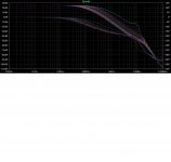
I'm sorry for not providing more responses for different CMiller values.
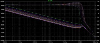
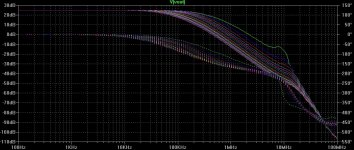
Attached open loop response with CMiller sweep from 15pF to 330pF with 15pF steps, it's also attached the LTSpice file.
Best regards,
Daniel Almeida
I'm sorry for not providing more responses for different CMiller values.
Attached open loop response with CMiller sweep from 15pF to 330pF with 15pF steps, it's also attached the LTSpice file.
Best regards,
Daniel Almeida
Attachments
Thanks for your reply,
I can try another way to break the loop like using a voltage source between Vout and the feedback resistor and then label this node for example a and then plot V(Vout)/V(a). But unfortunately the result is the same.
Best regards
Daniel Almeida
I can try another way to break the loop like using a voltage source between Vout and the feedback resistor and then label this node for example a and then plot V(Vout)/V(a). But unfortunately the result is the same.
Best regards
Daniel Almeida
Attachments
I can suppose that the defect can be caused by a phase rotation in any other stage, but reflects there. Try put some low capacitances in other places in the circuit.
Don't forget that an amplifier with such a high gain is prone to self oscillate at high frequencies per se.
An in practice, or real world, things are worse, because simulators ignore stray capacitances and inductances present in all electronic component, including circuit traces.
Don't forget that an amplifier with such a high gain is prone to self oscillate at high frequencies per se.
An in practice, or real world, things are worse, because simulators ignore stray capacitances and inductances present in all electronic component, including circuit traces.
Sure. Although I can't understand such acronyms, but in my experience, any unstable amplifier becomes more unstable under feedback closed loop, as at some frequencies the NFB can rotate to positive making an uncontrolled oscillator, including the possibility of blown the entire power stage.
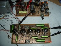
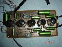
As an example, very different from it, I can show you an own design using tubes.
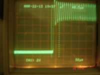
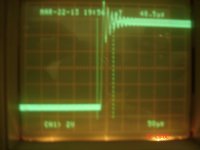
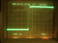
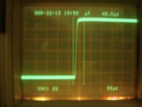
See photos 1 and 2. The circuit layout and the last, the schematic. See the capacitors labelled C9 and C10, they are the mica trimmers in the real circuit.
They are intended to neutralize the amplifier. It is a concept I took from RF circuitry. It consists of carrying a signal of equal amount from one circuit to other but 180 deg out of phase, so counteract the Miller capacitance.
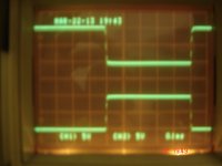
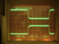
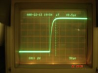
See the oscillograms of the true circuit the behaviour as the capacitors are increasing capacitor's value, the signal is 1KHz not limited inside the amplifier. Look how entire amplifier starts to oscillate at its own frequency when the capacitor are over-adjusted.
By this reason I suggest to try many capacitors in your circuit. When running my simulation after doing true circuit, the amp oscillates with 9.4 pf for both caps (C9 and C10) and very undercompensated for 9pf, a variation of only .4pF‼. Surely I could neglect if not doing the true circuit. Note no negative feedback at all, in fact a small positive FB from WCF to the cascode amplifier to increase gain. If overcompensated, it oscillates at open loop, imagine it in a close loop. Disastrous.
Enjoy simulations, but real world is different.
Osvaldo.
As an example, very different from it, I can show you an own design using tubes.
See photos 1 and 2. The circuit layout and the last, the schematic. See the capacitors labelled C9 and C10, they are the mica trimmers in the real circuit.
They are intended to neutralize the amplifier. It is a concept I took from RF circuitry. It consists of carrying a signal of equal amount from one circuit to other but 180 deg out of phase, so counteract the Miller capacitance.
See the oscillograms of the true circuit the behaviour as the capacitors are increasing capacitor's value, the signal is 1KHz not limited inside the amplifier. Look how entire amplifier starts to oscillate at its own frequency when the capacitor are over-adjusted.
By this reason I suggest to try many capacitors in your circuit. When running my simulation after doing true circuit, the amp oscillates with 9.4 pf for both caps (C9 and C10) and very undercompensated for 9pf, a variation of only .4pF‼. Surely I could neglect if not doing the true circuit. Note no negative feedback at all, in fact a small positive FB from WCF to the cascode amplifier to increase gain. If overcompensated, it oscillates at open loop, imagine it in a close loop. Disastrous.
Enjoy simulations, but real world is different.
Osvaldo.
Attachments
-
 Circuit.GIF37.6 KB · Views: 78
 -
 Oscilo 07.JPG132.8 KB · Views: 61
 -
 Oscilo 06.JPG128.4 KB · Views: 54
 -
 Oscilo 05.JPG134.9 KB · Views: 63
 -
 Oscilo 04.JPG132.4 KB · Views: 55
 -
 Oscilo 03.JPG134.8 KB · Views: 98
 -
 Oscilo 02.JPG133.4 KB · Views: 106
 -
 Oscilo 01.JPG134.1 KB · Views: 101
 -
 Amplifier & SEPIC.JPG139.6 KB · Views: 98
 -
 Amplifier 01.JPG156 KB · Views: 116
Last edited:
Hi Osvaldo,
This seems to work but that's strange I've never saw that in other amplifiers.
LTSpice circuit and open and closed loop response attached.
Best regards,
Daniel Almeida
This seems to work but that's strange I've never saw that in other amplifiers.
LTSpice circuit and open and closed loop response attached.
Best regards,
Daniel Almeida
Attachments
Hi Osvaldo,
This seems to work but that's strange I've never saw that in other amplifiers.
LTSpice circuit and open and closed loop response attached.
Best regards,
Daniel Almeida
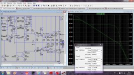
First you have to plot the loop gain.
Here with 15pF of the compensation caps and compensation of Q9 and Q10(drivers) it is perfectly stable with good PHM and GM. The peacking is comming from the triple output stage and it's good to use base stoppers for output transistors too, triple is known to be quite unstable if not tamed.
Attachments
Hello dadod and thank you very much for your help,
I've added a Miller compensation capacitor on the inverting side of the differential amplifier used in the VAS, Bob Cordell's circuit only shows one in the non inverting side.
Adding this capacitor the amplifier seems a little more stable, why?
Best regards,
Daniel Almeida
I've added a Miller compensation capacitor on the inverting side of the differential amplifier used in the VAS, Bob Cordell's circuit only shows one in the non inverting side.
Adding this capacitor the amplifier seems a little more stable, why?
Best regards,
Daniel Almeida
Hello dadod and thank you very much for your help,
I've added a Miller compensation capacitor on the inverting side of the differential amplifier used in the VAS, Bob Cordell's circuit only shows one in the non inverting side.
Adding this capacitor the amplifier seems a little more stable, why?
Best regards,
Daniel Almeida
Just simulate and see. More Phase Margin and more Gain Margin more stabe.
BR Damir
- Status
- This old topic is closed. If you want to reopen this topic, contact a moderator using the "Report Post" button.
- Home
- Amplifiers
- Solid State
- Open loop gain peaking