Hi guys!
View schemeatics this amplifier for which the author gives this
Specifications:
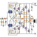
Power output is 60 watts into 8 Ω and 100 watts into 4 Ω loudspeaker.
Total harmonic distortion is less than 0.01 %.
Frequency range is within 20 Hz and 20 kHz.
The input sensitivity is in the vicinity of 750 mV.
The frequency characteristics lie in between 1 dB from 15 Hz to around 100 kHz.
If all this is okay?! What changes in the schematic needs to be done for this audio amlifier with power supply Ucc=+/-38V and with the output transistors MJ15003/MJ15004?
Thank you for your cooperation!
View schemeatics this amplifier for which the author gives this
Specifications:
Power output is 60 watts into 8 Ω and 100 watts into 4 Ω loudspeaker.
Total harmonic distortion is less than 0.01 %.
Frequency range is within 20 Hz and 20 kHz.
The input sensitivity is in the vicinity of 750 mV.
The frequency characteristics lie in between 1 dB from 15 Hz to around 100 kHz.
If all this is okay?! What changes in the schematic needs to be done for this audio amlifier with power supply Ucc=+/-38V and with the output transistors MJ15003/MJ15004?
Thank you for your cooperation!
Attachments
Last edited:
Supposing the transistors can support the voltages and currents, I don't see any important mod, perhaps R4 and R5 to maintain current in leds. The other parts are feed in constant current, so no mod necessary. Check also capacitor voltages rating (50V, mainly C6, C7 and C5).
But the schematic looks some strange. Did you forget R and a C in series from left side of R9 to ground? As is, the amplifier is unity gain.
But the schematic looks some strange. Did you forget R and a C in series from left side of R9 to ground? As is, the amplifier is unity gain.
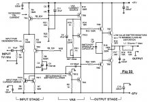
What are the transistors in the schematic?If you can use NPN/PNP power output transistors then you dont really need a quasi-complimentary circuit like this one. A basic Blameless type circuit will work fine.
thank you!
The schematic in post#1 is very similar to a circuit published in Elektor just after the release of the Crescendo and Mini Crescendo designs, except that instead of LEDs, the CCS were referenced with zener diodes. I had built several of those amps and thought they sounded very good for their time, especially with a fully regulated PSU.
Hi Samuel!The schematic in post#1 is very similar to a circuit published in Elektor just after the release of the Crescendo and Mini Crescendo designs, except that instead of LEDs, the CCS were referenced with zener diodes. I had built several of those amps and thought they sounded very good for their time, especially with a fully regulated PSU.
If you are unable to view the schematics.
thank you!
Hello,
Unfortunately, in post n°1, I'm afraid T10 is useless, with its Vbe = 0V.
That's it! is missing something, but what?

Hello!
Mr. Yaycee please show your PCB for this audio amp if you have one.
Thank you!
I don't but there are plenty of amps based around this sort of schematic. For example you may build the Destroyer X amplifiers (search this forum) using the MJ15003/4 output transistors if you wish.
Except others pointed there is issues in the output stage ,,,, this is short of copy of P68 from ESP pages which is class AB +B design and will have some issues when it comes to bandwidth ...it also seems that someone made patchwork between some circuits and expect forum people to debug the circuit ...
Hi jaycee!
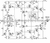
Mr Jaycee much I like your schematic up the so I ask for your PCB schematics! (see schematic-new)
The audio amplifier to put up your schematic and give an opinion as it sounds.
Thanks and Cheers!
P.S.
I apologize for my poor English!?
Mr Jaycee much I like your schematic up the so I ask for your PCB schematics!
(see schematic-new)The audio amplifier to put up your schematic and give an opinion as it sounds.
Thanks and Cheers!
P.S.
I apologize for my poor English!?
Attachments
Last edited:
Hi Samuel!
If you are unable to view the schematics.
thank you!
Did I say something irrelevant?
The design posted by jaycee is in fact a model design described as "blameless", designed by Douglas Self for his books like "Audio Power Amplifier Design Handbook" in all 6 editions.
If you want to get details, even see pics of modules based on this design, it would be smart to get a copy of the book, even second hand, read free excerpts or search the design on the net for yourself.
It is an extremely low distortion design when built with his specified components and boards but 2N3055s ? heh heh...nope! There are no PCB patterns in Self's books so if want someone to draw PCBs for you, you might have to look at other designs on the forum or the web.
Hi Gost22,
The circuit you published in your post #1 is very similar to the one
published in Elektor 1982 Summer Circuits, as Samuel has pointed out in
his post #6.But your circuit is lacking quite few resistors and will not work
as shown.
I also share the opinion with Samuel that the Elektor amp was quite good for
its time, and I believe that it is still quite good even by today's standarts.
I have modded that amp to work with NPN + PNP pairs and I have quite few
PCB's leftover.If you are, or anybody else, interested in having a go, I can
gladly supply the PCB's, just drop a mail to me ( selim_ardali at yahoo dot com ).
Cheers
Selim
- Status
- This old topic is closed. If you want to reopen this topic, contact a moderator using the "Report Post" button.
- Home
- Amplifiers
- Solid State
- Audio amplifier with 2n3005