Hi ,
I got a circuit on the sim that:
- cancels* distortion of the output stage
- cancels* offset voltage of the output stage
- cancels* occuring clipping (kind of severe distortion) of the output stage
- probably even cancels* overshoot on square signals ( not tested yet )
- makes it possible to run the output stage with very little or no feedback if desired.
I think I will post schematic soon")
Anybody interested to discuss this seriously ?
Or does anybody have an idea how I do that ?
*aproximately which means that on the sim, even under worst conditions as without feedback or while clipping, the output curve is absolutely matching the input curve
I got a circuit on the sim that:
- cancels* distortion of the output stage
- cancels* offset voltage of the output stage
- cancels* occuring clipping (kind of severe distortion) of the output stage
- probably even cancels* overshoot on square signals ( not tested yet )
- makes it possible to run the output stage with very little or no feedback if desired.
I think I will post schematic soon
Anybody interested to discuss this seriously ?
Or does anybody have an idea how I do that ?
*aproximately
which means that on the sim, even under worst conditions as without feedback or while clipping, the output curve is absolutely matching the input curve 
please be patient
Okay,
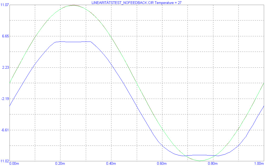
the red curve is the input , you do not see very much of it because it matches the output curve across the load which is green . The curve of the output stage is blue .
To see if the match is perfect, I made the amp a voltage follower, no voltage gain, only current.
The output stage is single ended classA and it is clipping and has got no feedback and has got terrible offset.
Still the output matches the input.
I did that to demonstrate what the circuit can do.
Of course the output stage can be with feedback and operated below clipping and with very little offset.
The rail voltages are 12V only because I just copied parts of the circuit from another of my amps.
Any circuit like this known to the public ?
I should call it "The mirror of the soul"
Okay,
the red curve is the input , you do not see very much of it because it matches the output curve across the load which is green . The curve of the output stage is blue .
To see if the match is perfect, I made the amp a voltage follower, no voltage gain, only current.
The output stage is single ended classA and it is clipping and has got no feedback and has got terrible offset.
Still the output matches the input.
I did that to demonstrate what the circuit can do.
Of course the output stage can be with feedback and operated below clipping and with very little offset.
The rail voltages are 12V only because I just copied parts of the circuit from another of my amps.
Any circuit like this known to the public ?
I should call it "The mirror of the soul"
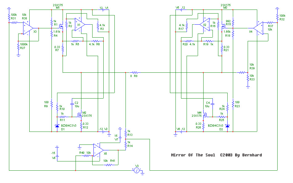
The upper left side is the SE classA output stage. The op amp x3 could provide voltage gain if desired.
X5 is an inverting buffer.
R13 & R14 make the heart of the circuit.
The inverted input signal and the signal of the output stage cancel each other, left over is the distortion of the output stage, divided by factor 2.
The distortion is reamplified by the upper left side which is again a SE classA output stage. X4 provides voltage gain 2x.
The right stage compensates the errors of the left side.
Including distortion, offset, clipping, and hopefully even overshoot.
 I know that the right side itself produces distortion.
But if the left side got some feedback so that it does good work, then the output of the right side will be only of a very very small amplitude, which means the new introduced distortion will be very very small too.
But nearly all of the left sides distortion will be canceled.
The circuit can be further improved, a differential amp and discrete parts instead of op amps could be used.
Because the output of the right side will be small except @ clipping, the right side rails can be as low as 7V or even less.
I hope this could be as good as the susy effect
Comments, critics and noble price welcome
X5 is an inverting buffer.
R13 & R14 make the heart of the circuit.
The inverted input signal and the signal of the output stage cancel each other, left over is the distortion of the output stage, divided by factor 2.
The distortion is reamplified by the upper left side which is again a SE classA output stage. X4 provides voltage gain 2x.
The right stage compensates the errors of the left side.
Including distortion, offset, clipping, and hopefully even overshoot.
I know that the right side itself produces distortion.But if the left side got some feedback so that it does good work, then the output of the right side will be only of a very very small amplitude, which means the new introduced distortion will be very very small too.
But nearly all of the left sides distortion will be canceled.
The circuit can be further improved, a differential amp and discrete parts instead of op amps could be used.
Because the output of the right side will be small except @ clipping, the right side rails can be as low as 7V or even less.
I hope this could be as good as the susy effect
Comments, critics and noble price welcome
Re: State space in idear
a please what

JensRasmussen said:Hi,
Nice work,
Is it based on a state space regulator?
\Jens
a please what
Bernhard said:Or does anybody have an idea how I do that ?
but does it make tea for me?
Netlist said:Did you use current feedback opamps?
/Hugo
No, everything is NE5532 for simplicity.
Bernhard,
I had thought that the cross-coupling topology would eliminate most distortion too.
See example on last page of the AD8610 datasheet:
http://www.analog.com/UploadedFiles/Data_Sheets/734705833AD8610_20_c.pdf
This seems very similar to your circuit. There may be other cross-coupled diagrams that are closer to yours.
As I looked more carefully, I found that distortion at/caused by the input circuitry doesn't cancel because it looks like the signal. And at the outputs (across R8) the feedback isn't an identical mirror. On the left the feedback is from the output of X3, and on the right, the feedback is from the inverted output of X4. (This would all probably work okay with ideal components.) In my mind, these two aspects make it not work perfectly. Also, others have indicated this cross-coupled circuitry only cancels even order distortion.
Analog Devices and Texas Instruments actually make single ended to differential out chips that they claim lowers second harmonic distortion (no cancels).
JF
johnferrier said:
As I looked more carefully, I found that distortion at/caused by the input circuitry doesn't cancel because it looks like the signal. And at the outputs (across R8) the feedback isn't an identical mirror. On the left the feedback is from the output of X3, and on the right, the feedback is from the inverted output of X4. (This would all probably work okay with ideal components.) In my mind, these two aspects make it not work perfectly. Also, others have indicated this cross-coupled circuitry only cancels even order distortion.
Analog Devices and Texas Instruments actually make single ended to differential out chips that they claim lowers second harmonic distortion (no cancels).
JF
John,
As I wrote, there is no feedback from the output stage to X3, just to simulate worst case conditions.
X3 needs his own feedback to be a voltage follower gain 1x.
Also this is not cross-coupled.
It is only from left side to right side, not vice versa. A one way ticket.
The function of the circuit is clearly defined, there is no question about how much coupling has to be.
R13/R14 are equal and gain of X4 is 2x gain of X3.
If the output stage is inside the feedback loop of X3, there is nothing left to worry about.
X5 could be a high end op amp like opa627 or it could be left out if X4 is a differential amp.
I also wrote this is a functional model and further improvements are possible.
Anyway it works perfect on the sim already.
- Status
- This old topic is closed. If you want to reopen this topic, contact a moderator using the "Report Post" button.
- Home
- Amplifiers
- Solid State
- no mercy distortion killer circuit