")
Hi everyone,
I have two LM4702 ICs but I've never used them, because I wanted to make a good simulation, but the models from TINA don't gave me that opportunity, because I don't have current in the Vbe multiplier circuit. I wanted to make a 4 output devices amplifier with BUZ900/905. But without correct biasing I can't know if the circuit will be stable with the values of gate stopper resistors and for the CMiller cap. Now about this subject LM4702 can be used with compensation types like IMC, TPC or TMC?
Best regards,
Daniel Almeida
tried out it TINA TI and found no oscillations but I dont even see the freq extension to 414khz its just there as is...thought some connections might be wrong but they are rightly placed. I removed the compensation cap and it was still working exactly like before. I think compensation cap is not affecting in Tina Ti for 4702.
but are those values above makes stable amp?
but are those values above makes stable amp?
Last edited:
guys any suggestions on the above value?
Any reason why you don't want to use the recommended values?
BTW Tina can of course simulate any network, but in this case apparently the comp pin input to the chip is not modelled in the chip's Spice model, rather a 'canned' compensation is assumed. Does the Spice model file say anything about this?
Jan
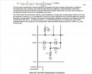
Cp2 is 12pf and so as cp1 has to be between 5 to 10 times lower so consider what pf value?
So I've studied how it has to be selected and read some where that the Cp1 has to be selected in such a way that the value to be stable in single pole compensation so my amp being stable at 47pf thought to select 3 times the value so 150pf so pole being at 414khz got the resistor value 2.5k I'm thinking to use it but just don't want to burn the amp
So I've studied how it has to be selected and read some where that the Cp1 has to be selected in such a way that the value to be stable in single pole compensation so my amp being stable at 47pf thought to select 3 times the value so 150pf so pole being at 414khz got the resistor value 2.5k I'm thinking to use it but just don't want to burn the amp
if you can see the post no #7 in this thread http://www.diyaudio.com/forums/solid-state/177734-questions-about-2-pole-compensation-vas.html
Its said that using 56 and 180 pF for a single bjt vas and my values seem pretty close to those as 47pf and 150pf may be little bit tighter...
But the question is that will there be any peaking in the audio band? Its said after 100Khz there would be a .8db peak which is still pretty acceptable for the performance improvement either in tems of HF THD reduction and or slew rate improvement...
tested it today amp was pretty heavily oscillating so had to go with single pole compensation but the moment I connected the single pole even then it was giving some small amount of oscillation. The amp was singing but 10 seconds later the 180 ohm 1/4 watt resistor which connects between the 2sc5171 and 2sa1930 burnt out I thought the bias would be more so reduced the pot to 0 and then checked again by resoldering the 180 ohm resistor even then the same scenario no idea what is causing the resistor to burn so now from the second time it just takes a second to burn.
what might have went wrong?
checked the driver power supplies ( OK )
checked the output power supply ( OK )
no shorts anywhere no signal cable cross over the power cables.
just now checked the output transistor pins on board by checking the short beep on the DMM and shockingly I found all the pins are shorted...
well now Its clear that the output stage transistors burnt out... so what could be the reason behind it?
I didnt tweak the pot in the beginning and I believe the pot was at 1k ohm... I believe more bias has burnt things or is there anything which is making that hum to happen...
http://www.connexelectronic.com/documents/LM4702_BPL_Audio_Amplifier_Module.pdf
i have reduced the bias this time and powered up now it has strange phenomena like when i turn on the amp it will neither oscillate nor it will show the output but there are few things happening
the 180 ohm resistor is heating up pretty high as if it would blowup so I took 1k resistors and paralleled 5 of them to get roughly 200ohms and I found a strange phenomena as
when I power up the amp nothing will sound like even after giving the signal it doesnt sound .. checked the power supply both for driver and also for the output
but the strange thing is that when I turn off the amp after few seconds I get small durations of less than 1 second in which the audio signal is present and its pretty clear. This will repeat in cycles of 2 seconds for about 5 times and then turns off..
I really didnt understand what went wrong in the circuit... It has a stable bias of 125ma..
- Status
- This old topic is closed. If you want to reopen this topic, contact a moderator using the "Report Post" button.
- Home
- Amplifiers
- Solid State
- two pole compensation for lme4702 lme49830