Hi guys!
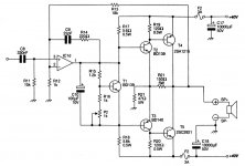
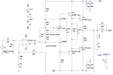
Will I create this amplifier under this schematics. Seeking your opinions on this audio amplifier. What can change of the schematics to improve its features?
Otherwise, instead of 2sc2921/2sa1215 want to use mj15003/mj15004 ate possible to do it without making any changes to the schematic?
What OP for IC1d in this schematics is best used?
Thank you for your cooperation and help!
Attachments
Last edited:
seems to lack an vas stage.....,voltage swing will be the maximum ic1 can put out.If you use ne5534 you will get 30v peak to peak and that wont get even near 100w at 4r,maybe 25watts max
Look at it again - the CFP output stage does not have a gain of 1. However, this amp can be a problem to stabilize as this sort of output stage does like to oscillate sometimes. Then there is the problem of thermal stability which is only marginally addressed in the design. A different combination of driver and output transsistors may not be thermally stable. In particular, MJ15003/4 will not only be thermally unstable but also may prove marginally driven due to a much lower current gain and lower ability to keep this gain at higher currents. They are also slower than the 2SA/2SC parts by a factor of 6-10, so the output will have the classical problem of driving slow devices with fast ones, and the actual bandwidth will be yet lower because the output stage has gain - expect instability.
There is also an obvious error in the schematic, a resistor is labelled 5.6 ohm instead of 5.6k.
Last edited:
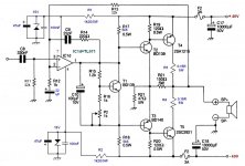
So for Ucc for IC1d (Ne5534 or TL071) should be: Ucc = + /-15V. For broadcasters, the output transistors should be placed 0.15 R/5W.
See the new schematics.
Thank you!
You will accomplish nothing with 0.15 ohm resistors in the collectors, they have to go into the emitter side (between power supply line and emitter). It may require a higher value (0.22-0.33 ohms).
The voltage drop resistors can't be 0.5W if they dissipate 0.53W, resistor power dissipation is the absi=olute maximum assuming low resistor case temperature. Under normal circumstances calculate dissipation, and use resistor at least 2x and preferably 3x that - in your case 2W resistors.
I tried a few similar circuits early on as I liked the idea of using an opamp for the small signal stage. Unfortunately it just doesn't work reliably - with gain in the output stage it is a nightmare to get it stable.
I also wouldn't use BD139/BD140 as drivers. MJE243/253 would work better.
I also wouldn't use BD139/BD140 as drivers. MJE243/253 would work better.
If you use a high voltage opamp such as the OPA452 or OPA453 (supply up to +40V for both) you don't need the feedback resistors in the output stage or the Zeners e.a. for the opamp.
For my adventures with opamps in a power amplifier, look at this thread:
http://www.diyaudio.com/forums/solid-state/194453-very-simple-class-b-amplifier.html
For my adventures with opamps in a power amplifier, look at this thread:
http://www.diyaudio.com/forums/solid-state/194453-very-simple-class-b-amplifier.html
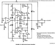
Here is a version of my circuit using a +40V supply, an OPA551 opamp and discrete pre-drivers and drivers transistors. Unfortunately, the output cannot be driven to the rail voltages which means that 100W is no longer doable. It gives out 75W into 8 ohms, a loss(!) of about 1.2dB. However, THD is predicted to be 0.0019% at 1kHz and 0.035% at 20kHz. I doubt that an NE5534 can match that.
Attachments
Such opamps are usually expensive and limited - there is not really any point in using them for this task, you may as well just use a few more transistors and make a completely discrete amp.
Or if you really want something like this, use a device made for the job such as LM4702.
Or if you really want something like this, use a device made for the job such as LM4702.
The OP wanted to explore the possibilities of using opamps in power amps. There are lots of threads about discrete amps.
Using an LM4702 is a good idea, but not much fun - too easy.") Also, TI only supplies the SPICE model for it in encrypted form, which is not much use without PSPICE or TINA-TI.
Also, TI only supplies the SPICE model for it in encrypted form, which is not much use without PSPICE or TINA-TI.
In my rush to put up post 9 before dinner, I messed up a bit. One does not keep show up late for dinner, hehehe. The OPA551 can only handle +30V supply. Apologies for that...
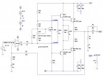
I have run the simulation again using the OPA454. It can handle a +45V supply. Here is the amended circuit.
Output voltage swing is not great. The +45V supply only gives 70W into 8 ohm. THD is 0.0019% at 1kHz and 0.064% at 20kHz. Frequency response is not ultra flat, being 0.27dB down at 20kHz.
Oh yes, in my part of the world the OPA445 is about US$10.40 while the TL071 is about $4.50 - not that great a difference when you consider all the other costs in an amp.
Using an LM4702 is a good idea, but not much fun - too easy.
Also, TI only supplies the SPICE model for it in encrypted form, which is not much use without PSPICE or TINA-TI.In my rush to put up post 9 before dinner, I messed up a bit. One does not keep show up late for dinner, hehehe. The OPA551 can only handle +30V supply. Apologies for that...
I have run the simulation again using the OPA454. It can handle a +45V supply. Here is the amended circuit.
Output voltage swing is not great. The +45V supply only gives 70W into 8 ohm. THD is 0.0019% at 1kHz and 0.064% at 20kHz. Frequency response is not ultra flat, being 0.27dB down at 20kHz.
Oh yes, in my part of the world the OPA445 is about US$10.40 while the TL071 is about $4.50 - not that great a difference when you consider all the other costs in an amp.
Attachments
Last edited:
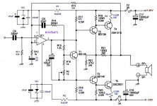
Ilimzn, so this should be the schematics:
I ran a simulation of the circuit in LTspice. I didn't add the Zener PSU for the opamp but simply used another split supply. Also, I had to substitute the output devices for the MJ802/MJ4503. There are no SPICE models available for the Sanken 2SA1215 and 2SC2921 devices. I tried the MJL1303/MJL2381 but they didn't work with the Vbe multiplier as it is and I didn't investigate it further. I also increased the value of the decoupling capacitor on the input. It was way too small.
The results were:
Power : 80W into 8 ohm
THD: 0.021% at 1kHz;
0.85% at 20kHz
The high THD at 20kHz looks light it might be caused by the slew rate being too low.
Attachments
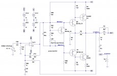
Upon checking the simulation again, I noticed that with the bias pot at 80% the amp is in fact running in class A. It needed to be set for proper class B operation.
It seems that the resistors values around the Vbe multiplier needs some work. Setting the pot below 65% or above 85% causes the circuit to stop working. Actually it's worse than not working - one output transistor would be off with the other one running very hot, biased at 5A or so.
In Class B I could not get the bias current below 900mA. Each output transistor consumes 35W at idle. Even extremely fine tuning of the bias pot setting does not help. I gave up at 65.55%. Back to the drawing board?
Last edited:
Hi mr Ingenieus!
I have power supply Ucc=+/-37V with about 7A. I have the same speakers with impedance of 4ohm and frequency characteristics from the 40 .. 18000Hz to +/-2dB! Give your recommend an audio amplifier class AB (schematics or project) with a pair of output transistors in TO3 package (such as MJ15003/4 or MJ4502/ 802) that I want to use it for home use.
Thanks for the help!
I have power supply Ucc=+/-37V with about 7A. I have the same speakers with impedance of 4ohm and frequency characteristics from the 40 .. 18000Hz to +/-2dB!
Give your recommend an audio amplifier class AB (schematics or project) with a pair of output transistors in TO3 package (such as MJ15003/4 or MJ4502/ 802) that I want to use it for home use.Thanks for the help!
Last edited:
There's likely a contribution from the TL071's 10MHz GBP yielding undesirably low excess loop gain. This THD rise with frequency is normal for audio circuits and Bruno Putzey's discussed it extensively. Don't have a link handy but it shouldn't be hard to find his derivation that 18+MHz min is desirable. The LME49710 and 49720 are good defaults for this sort of amp (and most other audio circuits too). Generating the bias current with an LM334 rather than a resistor to rail will probably yield slightly more linear operation. Sanken's STD03N and STD03P complimentary pair is worth a look for improved thermal tracking in the bias as well.The high THD at 20kHz looks light it might be caused by the slew rate being too low.
Not to rain on the parade, but chipamps are tough to beat as output stages; cheap, mechanically simple, current limited, thermally protected, and their local feedback loop doubles as a VAS stage. For 100+W look at National, er, TI's BPA200 app note. Though an LME49720 and an LM3886 per channel makes an easy biamp with 112W total power.Back to the drawing board?
Last edited:
what's wrong?Troublemaker, the 2N3771 is only a Vceo (sus) of 40V, and 200Khz.
The 2n3771 is one of the very highest SOA @ 150W @ 100Vce
Not many To3 can match that !
It is also very robust, maybe something to do with the high voltage of the knee in the SOA.
As for fT, you must be looking at a poor unlicensed copy.
Most quote around 800kHz and that allows good performance in an audio amplifier running at up to +-70Vdc.
- Status
- This old topic is closed. If you want to reopen this topic, contact a moderator using the "Report Post" button.
- Home
- Amplifiers
- Solid State
- 100W audio amplifier with Ne5534