Is this possible ?
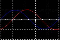
Same signal is fed to the circuit
Blue trace is the output of circuit
Red trace is the DIRECT input to circuit
Blue exits ahead of Red ?
In TV we can 'genlock' a sync generator to put out 'advanced sync' which _seems_ to make a signal before it exists but it's an illusion. The 'advanced' output is actually delayed for s LONG time. If the frames were numbered it would be readily apparent.
If you want to delay a signal for an arbitrary length of time it's easy in digital. If you want a _phase_ shift AND work with variable frequencies it's much more difficult.
G²
Thanks for the responses so far ")
DF96 says 90 + SI ?
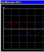
Ahh, good point, it "might" be that ? But please see my new screenie with the Same setup, but Osc showing from start position. Do you still think the output is advanced, or ?
I didn't actually have anything in mind, i'm only tinkering around with some unconvential types of my designs, to see what happens.
Michael Bean says 315 PL ?
I'm waiting to hear back from Area 51
Originally Posted by Michael Bean
Sim is showing a steady state signal with 315 degree phase lag?
DF96 says 90 + SI ?
Originally Posted by stratus46
In TV we can 'genlock' a sync generator to put out 'advanced sync' which _seems_ to make a signal before it exists but it's an illusion. The 'advanced' output is actually delayed for s LONG time. If the frames were numbered it would be readily apparent.
Ahh, good point, it "might" be that ? But please see my new screenie with the Same setup, but Osc showing from start position. Do you still think the output is advanced, or ?
If you want to delay a signal for an arbitrary length of time it's easy in digital. If you want a _phase_ shift AND work with variable frequencies it's much more difficult.
I didn't actually have anything in mind, i'm only tinkering around with some unconvential types of my designs, to see what happens.
Originally Posted by DF96
Output is 90 degree lag, plus signal inversion?
Michael Bean says 315 PL ?
Civilian versions of SPICE can't do Time Machine simulations as the code for that is only included in the military versions.
I'm waiting to hear back from Area 51
Attachments
Last edited:
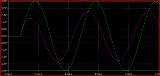
a high pass/differentiating circuit is described as having "phase lead"
does't violate causality
heuristically the plot below, starting from zero steady state you can see the purple high pass "getting ahead" of the green input in the 1st few 100 uS
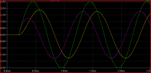
the 2nd plot adds the same fc low pass - yellow "falls behind" the green input sine, ends up "lagging" by ~90 degrees
does't violate causality
heuristically the plot below, starting from zero steady state you can see the purple high pass "getting ahead" of the green input in the 1st few 100 uS
the 2nd plot adds the same fc low pass - yellow "falls behind" the green input sine, ends up "lagging" by ~90 degrees
Attachments
Last edited:
I had a box for something completely different that required an exact 90° phase shift of a 60 Hz sine. In analog that can be done with an opamp integrator which is a precise 90° because it's the definition of an integrator. Because there is a cap in the feedback loop the _amplitude_ will change with frequency but the _phase_ shift is exactly 90°. The goal of that box was to create a cosine ramp so that you could get linear power changes phase triggering a lamp dimmer with 4 quadrant control all the way to 0.
G²
G²
Choose any negative tone on your vector signal generator.
Quadrature then rotates counterclockwise...
Negative frequency seemed (and was) meaningless to me
looking only at one output and perhaps it's inverse copy.
But when required to specify how the 90 and 270 degree
outputs should lead or lag, it suddenly all made sense.
It's a chirality thing, you wouldn't understand...
Last edited:
- Status
- This old topic is closed. If you want to reopen this topic, contact a moderator using the "Report Post" button.
- Home
- Amplifiers
- Solid State
- Time Reverser circuit !