How many 2N3055's do you have? And any good medium power (TIP41C, etc) to drive them with?
Assuming I had enough of them (and that they were free) I would use three in parallel per side and run off a +/-28V supply (20-0-20, 5A toroid). Use TIP41C drivers and 2N5401/5551 predrivers in a TRIPLE. Yes, a triple. The output schematic would look like the Phase Linear 400 with lower rails. It works with low gain transistors like the 3055, will drive 2 ohms, and it's (almost) foolproof. Standard diff pair front end and single ended VAS with a bootstrap (copy from the DX amp, it's as good as you need).
Assuming I had enough of them (and that they were free) I would use three in parallel per side and run off a +/-28V supply (20-0-20, 5A toroid). Use TIP41C drivers and 2N5401/5551 predrivers in a TRIPLE. Yes, a triple. The output schematic would look like the Phase Linear 400 with lower rails. It works with low gain transistors like the 3055, will drive 2 ohms, and it's (almost) foolproof. Standard diff pair front end and single ended VAS with a bootstrap (copy from the DX amp, it's as good as you need).
There is Elvee's circlophone. It is capable of lower loads such 2 ohms. But it uses single pair at output, though you can't reach to 120W. 2n3055's SOAR limit doesn't allow to such current on a single pair.
http://www.diyaudio.com/forums/solid-state/189599-my-little-cheap-circlophone.html
http://www.diyaudio.com/forums/solid-state/189599-my-little-cheap-circlophone.html
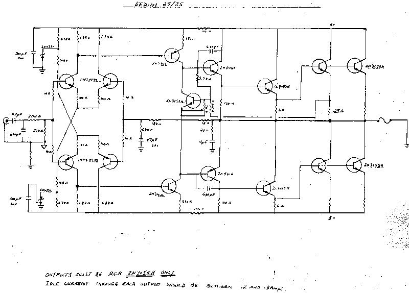
Bedini's little amps sounded good in their own way http://www.diyaudio.com/forums/atta...335738011-bedini-10-10-class-bedini-25-25.jpg
i have BC, 2n5551, 2n5401, 2sc945, 2sa733 and ... too
As pointed by other members some decent drivers are necessary ,
adequate models can be TIP31B/32B , TIP41B/42B , BD241B/242B .
BD243B/244B , BD711/BD712 and eventualy if correctly cooled
BD442/443 can be used as well.
Also , what will be the usage ? If it s for public adress it doesnt
need to be as complexe as if it s for hifi use.
Hello
Here's amp schematic who use the 3055 transistors and give a high output, I've simulated it and it's work good with low thd.
Bye
Gaetan
He will need a quasi complementary design , simple if possible...
Last edited:
i have 30 pcs 2n3055 and 10 pcs tip41c
If you dont have a complementary for the TIP41C , a TIP42C or even B
this can be solved eventualy with a triple emitter follower pair for the
positive side using 2N5551 + TIP41C + 3 X 2N3055 and a composite
PNP using 2N5401 + TIP41C + 3 X 2N3055 for the negative rail side.
I ll do some simulations to "test" the configuration with a generic
schematic and ill try to give you the results soon.
thank you so much
")
Here is a design that I simulated in Circuit maker,
http://www.diyaudio.com/forums/solid-state/167394-quasi-amplifier-beginners-10.html#post2812503
The schematic is in the next post.
I haven't built it yet but it is a basic classic design that may help you to get an idea about how to reach your goal.
The whole thread is worth a good read.
All I did was basically tweak a design that is already in the thread to perform well at the 1 to 2 ohm load range.
It is also biased quite high (250ma per device) as well for class A mode of operation at low levels but this can be easily adjusted for lower bias levels.
This is a very powerful design with high voltage rails.
It should be very easy to adapted for lower voltage rails for only 120watts of output (maybe).
I quoted maybe because it was tricky to get it to simulate properly at lower voltages.
I also did a design based on the JLH amplifier design for such low impedance's as well.
It was to use 8 (or more) pairs of 2N3055's on the output.
It was purely a Class A design and I believe the 100watt range was my target as well a low impedance for driving my ESL systems.
I found that by the curves the more output devices I used the more linear the circuit could be (lower THD).
This is because the devices HFE gets lower as they conduct more current as already mentioned.
I was actually going to use some 8 to 16 pairs of TIP3055's becuase I could get them for like $.40 a piece or so and their curves showed to be more linear than a normal TO-3 2N3055's according to the RCA semiconductor handbook.
I don't have that schematic handy at the moment and I thought that I had posted it.
But, I couldn't find it last time I went looking for it because I still want to build it.
I am sure that I have it in my archives somewhere though.
I will try to find it as there are a few other of my designs that I need as well and they are on another hard drive that is not hooked up at the moment
Cheers !!
jer
"Assuming I had enough of them (and that they were free) I would use three in parallel per side and run off a +/-28V supply (20-0-20, 5A toroid). Use TIP41C drivers and 2N5401/5551 predrivers in a TRIPLE. Yes, a triple. The output schematic would look like the Phase Linear 400 with lower rails. It works with low gain transistors like the 3055, will drive 2 ohms, and it's (almost) foolproof. Standard diff pair front end and single ended VAS with a bootstrap (copy from the DX amp, it's as good as you need). "
Basically, I agree.
I would use only two pair of outputs though, and use another pair for drivers. This would look a lot like half the output stage of the McIntosh MC2300, rated at 300W into the 1Ω primary of its output autoformer.
I actually rebuilt an MC2300 with Motorola 2N3055s in the late 70s, they don't work well when you pour a pitcher of Coke into them while running!
After the rebuild, they only problem the club had was the dustcaps blowing off their 15" Gauss woofers.
McIntosh uses 0.33Ω emitter resistors on the outputs, and either 0.56Ω, 0.62Ω or 0.68Ω resistors on the drivers. The predrivers had 100Ω resistors.
You could download a McIntosh MC2100 schematic to see the general idea, although I too would use the DX amplifier front end (Mac used resistors for current sources pulled up to 100V supplies!). The Mac schematic also shows current limiting for short circuit protection.
Last edited:
- Status
- This old topic is closed. If you want to reopen this topic, contact a moderator using the "Report Post" button.
- Home
- Amplifiers
- Solid State
- 120 watt amp in 2 ohm loud with 2n3055