...amplifiers do indeed clip when playing well-recorded program material at realistic SPL levels with typical loudspeaker sensitivities...
I need some further explanation on this. An example:
A power amplifier that takes e.g. 1.5V input before clipping into the given load.
I adjust the volume control to the volume I normally listen (or a bit above).
I play a -0dB sine wave from a test CD and measure e.g. 150mV at the preamp output.
How would I now ever drive the amp into clipping ?
Brad can you share your circuit - that way I can add it to the sim I posted earlier.
I would say, since the ultimate goal here is a BIC CM for discrete CFA audio amplifier application, we need to sim with realistic currents, and my thinking is that this somewhere between 1 and 5 mA.
I would say, since the ultimate goal here is a BIC CM for discrete CFA audio amplifier application, we need to sim with realistic currents, and my thinking is that this somewhere between 1 and 5 mA.
I've done a quick sim and am struggling to see what it brings to a straight 3 or 4 transistor mirror. Bandwidth is slightly better, but its more peaky, and distortion is not as good as the 4 transistor version (30ppm at 5mA).
The cascode certainly adds nothing in terms of bandwidth in a practical amplifier because of the capacitive loading on the cascode output will dominate.
Any thoughts?
Your observation is correct, it doesnt bring anything to the table when used in CFA amp where the loading of the outputstage dampens its performance. There is also no point in using any current mirror for that matter. I mentioned it because if one were to design no feeedback current conveyor. In this case and with light load it performs well.
If you look In circuit i posted, i use them as well.
If i remember right, i Got at enhanced phase margin
Which circuit ?
Here is the mirror sim file updated with the Boxall cascode
BASIC WITH HELPER
Total Harmonic Distortion: 0.009537%
4 TRANSISTOR WILSON
Total Harmonic Distortion: 0.001217%
BASIC
Total Harmonic Distortion: 0.497355%
BOXALL CASCODE
Total Harmonic Distortion: 0.009121%
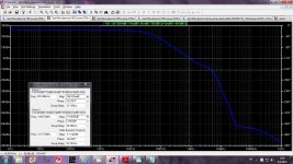
I've attached the responses in the pdf - the traces correspond to the .asc Vo numbers.
Interesting, sim responses are a little different to real life. I showed the measured response of mirrors in another thread, all displayed peaking except the standard one. Maybe due to the transistors used.
Bob, I'd say given how easy it is to design in headroom in the small signal stages, in most cases you are going to have to deal with it in the power amp, and there, ultimately its the rail voltage and current delivery that sets the limit for a given load.
(Caveat: I note that there are many RIAA amplifiers that have dismal overload charateristics - John Atkinson has found a few with <10dB and I saw one IIRC that he measured with just 3dB - really unacceptable nowadays IMV since it is so easy to design to accomodate 25 or 30dB peaks in a RIAA)
Bonsai,
I agree that the place where clipping usually must be managed is at the power amplifier, for the reasons you described. BUT, I believe it is best NOT to let the ultimate clipping limit of the rail voltage or short-term current be the limit. The best approach is to have a clipper ahead of the feedback-looped portion of the power amplifier-proper to clip the signal JUST before it hits the rail limit. When the rail limit gets hit, nasty clipping can occur and rail ripple can intrude in many designs.
Having said that, I also believe that amplifiers should be designed to clip as cleanly as possible.
Cheers,
Bob
Your observation is correct, it doesnt bring anything to the table when used in CFA amp where the loading of the outputstage dampens its performance. There is also no point in using any current mirror for that matter. I mentioned it because if one were to design no feeedback current conveyor. In this case and with light load it performs well.
I think a triple will go someway to solving this issue. Also, as I noted earlier, in a practical power amplifier, the TIS mirror will need to be run at a decent current - IC opamp level currents are not going to cut the mustard.
I think a triple will go someway to solving this issue. Also, as I noted earlier, in a practical power amplifier, the TIS mirror will need to be run at a decent current - IC opamp level currents are not going to cut the mustard.
The question is whether a mirror is necessary in CFA TIS, I think not. In none of my 100s of sims or practical circuits did a mirror improve performance. Have you found it improves performance ?
Yes, I'll try to get to that soon. Remember that particular example was just done to dramatize the output capacitance effect. Given some general requirement I could come up with some suggested topologies, but that turns quickly into an article-sized effort. By the way, after realizing above that the primary parallel noise at the inverting input of a CFA is from the mirrors, my enthusiasm for a different input gm core went down by about 3dB. Still worthwhile and as usual probably not new, but there's less of a compelling need 🙂Brad can you share your circuit - that way I can add it to the sim I posted earlier.
Current Mirrors
back ground -- look it up and decide what benefits can be obtained. Here are 2 pages of the Wireless World article:


Thx-RNMarsh
back ground -- look it up and decide what benefits can be obtained. Here are 2 pages of the Wireless World article:
Thx-RNMarsh
perhaps you have not tested the circuits for voltage sensitivity? Pretty important, dont you think, for unregulated PS in power amps?
Thx-RNMarsh
Thx-RNMarsh
Appeal for a glossary
I started to re-read the beginning of this thread and realized that many of you may take for granted that we all know what various abbreviations mean, or at least what they say spelled out. I suppose with enough searching term by term one could be so apprised, but perhaps someone could do us the service of a table, or point to such a list that may exist in some other thread.
I started to re-read the beginning of this thread and realized that many of you may take for granted that we all know what various abbreviations mean, or at least what they say spelled out. I suppose with enough searching term by term one could be so apprised, but perhaps someone could do us the service of a table, or point to such a list that may exist in some other thread.
The question is whether a mirror is necessary in CFA TIS, I think not. In none of my 100s of sims or practical circuits did a mirror improve performance. Have you found it improves performance ?
The mirror response is flatter and wider than a straight common emitter stage (with or without beta enhancer) and I think that's the bit that interests me. If you end up with a -3 dB corner at a few kHz, which is generally the best I have seen with the CE type TIS, it kind of defeats the object of CFA IMV.
OTOH, response that is flat out to 100's of kHz seems relatively easy with mirrors. But of course, you don't have the linearizing effect of Cdom or the higher loop gains of VFA, hence the quest to find a very linear mirror structure.
Last edited:
Use the full name first time in the text with the abbreviation in parenthesis.
Then the abbreviation can be used at will and everyone knows what is being referred to.
No confusion.
Then the abbreviation can be used at will and everyone knows what is being referred to.
No confusion.
That is devoutly to be wished.Use the full name first time in the text with the abbreviation in parenthesis.
Then the abbreviation can be used at will and everyone knows what is being referred to.
No confusion.
Sidney Harman told one of his favorite stories about when he served under President Carter as deputy undersecretary of commerce (iirc). He's sitting at a conference table surrounded by various august veterans of Washington D.C. One after another is spouting with phrases full of acronyms and abbreviations, of which Sid has no knowledge. Finally he addresses one of them, and questions him: "But have you considered the impact that the GEL is going to have on the FSP of the DRN??" The addressed one says, "Sir, I will proceed to given that my immediate attention."
Of course Harman just made his abbreviations up on the spot, and gambled that he wouldn't be asked what the hell they meant. He said after that he never feared what might happen at such meetings.
I should be somewhat more charitable about this, since the detail of the return of the Boxall auxiliary transistor's base is to the commoned bases of the e-follower-enhanced mirror. So the two main mirror transistors tend to have approximately constant Vcb and Vbe established, although they are not identical (left-hand one's [Qin2] Vcb is the Vce of the e-follower [Qin1], whereas the right-hand one's [Qout] is about zero. This will lead to a quiescent operating temperature difference and thus a Vbe difference, but it shouldn't be too serious).A Boxall stuck on to the output of a fairly standard mirror. Oh well, no patent will surprise me anymore 🙄
Of course when used in an amplifier with overall feedback, and with a high Z internal node fed by the mirror(s), there will be a large voltage swing for a small current swing except when slewing or at high frequencies. The Boxall pair buffers this swing from having much effect on Qout.
Attachments
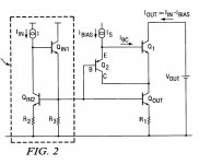
An enhancement of the patented mirror under discussion
This is clearly related to the patented e follower enhanced mirror with Boxall cascoding, but a small change from that embodiment shown improves things significantly. A needed ~1.5V level shifter is easy to realize as the currents involved are small --- in one embodiment a high-brightness LED (nominal 2.1 V forward voltage at rated current) and bypass C requires a small current besides the Ib of the auxiliary Boxall transistor, to be about the right voltage.
The distortion is dominated by 2nd, which suggests that things can get even better in a complementary arrangement if the positive-polarity circuit behaves similarly. In any event, from a distortion perspective, things will likely be dominated, in any case, by the voltage variable C of the following stage.
The resistor values are not as critical as the significant figures might suggest --- just a habit of using E96 values. Also the 300 fF shunt C is just shown for formality, as what is required for flat frequency response. Real current sources will also entail some performance degradation.
Attachments
The distortion is dominated by 2nd, which suggests that things can get even better in a complementary arrangement if the positive-polarity circuit behaves similarly.
V.Good improvement. Would you draw for us the complimentary version, pls?
Thx-RNMarsh
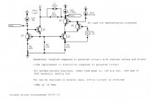
This is my last modification of the CFA amp. The gain stage is a current conveyour, output stage is my implementation of the HEC OPS.
The phase margin is 86 degree, gain margin is 11dB
THD1k is 2.6ppm, THD20k is 5.6ppm, THD40k is 25ppm all at 50W on 8ohm load
The loop gain(LG) could be changed by changing R36 value.
Interesting that distortion is going somewath down with lower LG.
BR Damir
P.S. Manso, using your CM enhancement distortion is going down but slightly
Attachments

This is my last modification of the CFA amp. The gain stage is a current conveyour, output stage is my implementation of the HEC OPS.
The phase margin is 86 degree, gain margin is 11dB
THD1k is 2.6ppm, THD20k is 5.6ppm, THD40k is 25ppm all at 50W on 8ohm load
The loop gain(LG) could be changed by changing R36 value.
Interesting that distortion is going somewath down with lower LG.
BR Damir
P.S. Manso, using your CM enhancement distortion is going down but slightly
Also looks V.Good. Will pcb become available so it can be built and measured against the SIM version?
Thx-RNMarsh
Last edited:
- Home
- Amplifiers
- Solid State
- CFA Topology Audio Amplifiers