Hi, I have been looking at building myself a version of the P3A amp from Rod's pages, but I have a few questions about the design and it's implementation.
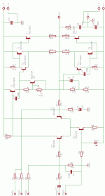
Firstly, Rod states that teh maximum rail voltage which should be used with this design should be +/- 40V to get about 100W into an eight ohm load. However, as I will be building this with the newer onsemi output devices and drivers which are rated at up to 230V (I think, that is just a figure from memory, it could be 350 but I don't think it is any lower than 200V) as well as doubling the number of output devices, would it be safe for me to run this design on higher rails? As I was considering going as high as +/- 50V to get around 125W out of each channel.
The second point is concerning the aditional output devices. Now, in the article, Rod states that the high frequency rolloff of the amp is coverned by a descreet capacitor added to aid stability. So, would I be correct in thinking that the extra juction cappacitance seen by the drivers from the extra output transistors will not have to great an effect on the amps frequency responce as this is not the limiting factor governing the circuit design?
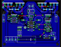
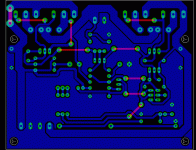
Anyway, I have included my updated scheematic below, along with a provisiona copy of the PCB layout and would apreciate comments on both, as well as teh questions posted above.
Andrew.
Attachments
Here is my provisional PCB layout to with the above design. I intend on testing this for a single channel on a single sided PCB, but if it goes well, I intend to make the board double sided and get few professionaly made.
Also, if anyone knows a good scource of low value, high power resistors that can be end mounted in the Uk can you pleasse post here, as I am having trouble finding any at the moment.
andrew.
Also, if anyone knows a good scource of low value, high power resistors that can be end mounted in the Uk can you pleasse post here, as I am having trouble finding any at the moment.
andrew.
Attachments
bigparsnip said:Here is my provisional PCB layout to with the above design.
andrew.
andrew, that's one pretty design job. If you don't mind, can I ask what software package you used for it?
I am running protel dxp demo and had a hard time to find out how to "enlarge" the traces and kind of make it fill-out empty spaces like you did.
Any tip would be appreciated.
I did that one with the trial version of eagle ( http://www.cadsoftusa.com/), which is a joy to use, but is unfortunately rather limited with some of the design work you can do (only two layers, and max PCB size of 100 X 80 mm). So I also 'upgraded' recently to a coppy of protell 99SE, but I am also finding the lerning curve a little steep (I have just about managed work out how to transfer a schematic to PCB drwing now, but it seems to take a while to set up if you don't have any of your own libraries to work form). As far as the fills go in protell, I'm afriad I can't help you with that yet, but I should get round to having a bit more explore with it soon, and if I find out how I'll let you know.
Hi, the driver transistors will also be the new, very well specified, models MJE15034 and MJE15035 from onsemi, both being rated at 350V (it was 350 for the outout devices too, 230W for their power handling) and up to 4A each.
What about the small signal transistors that are on there? Is there anything better thant he BC546 to use, as I always thought that these were a cheep generic component, so there must be something that would be better out there to replace them?
What about the small signal transistors that are on there? Is there anything better thant he BC546 to use, as I always thought that these were a cheep generic component, so there must be something that would be better out there to replace them?
Hmm, not the fastest devices in the world (only 50MHz, compared to the 35MHz for the output devices seems a little slow) but I guess they would more than do their job properly and the specs for current and voltage handling seem ok. I guess I could always give a few different types a go and see if any are noticably better in there.
I use 2N5551 small signal transistors, in my P3A running at +/-52V.
http://www.fairchildsemi.com/ds/2N/2N5551.pdf
/Freddie
http://www.fairchildsemi.com/ds/2N/2N5551.pdf
/Freddie
I found something else now, it's a toshiba part, the 2SC2240. It's rated at 120V, at 100MHz, with a typical HF in the 200-700 region, so I guess this would be my best choice so far. Has anyone else used or seen these about before though?
2SC2240 data sheet
2SC2240 data sheet
I use them all the time with great results. I've never had one fail even at rails up to 80V! The 2SA970 is the PNP compliment. They are very wide bandwidth and quiet too. Try 'em you'll love it.bigparsnip said:I found something else now, it's a toshiba part, the 2SC2240. It's rated at 120V, at 100MHz, with a typical HF in the 200-700 region, so I guess this would be my best choice so far. Has anyone else used or seen these about before though?
2SC2240 data sheet
Re: HO P3A
Parsnip,
First, make sure and credit Rod for any work, a link to his site would be the right thing to do.
Regarding your circuit, use Toshiba 2SC1775As for the differential pair, trust me on this, the sound improvement is not slight. They are rated >100v. The pin config is different from most, so double-check your board. Also you MUST match the pair as the 1775's gain varies
For C4 and C5, I'd use a minimum of 100uF. The amp tends to sound a little thin otherwise. The same goes for the input cap, a large (>=4.7uF) film cap works well. For best sound, use a non-polar for C4, Black Gate is great, Nichicon Muse series sound nice as well.
Your chosen Onsemi drivers will work fine.
But all that being said, I would stick to Rod's recommended max rail voltages. The slight increase in output is simply not worth it. As advertised on Rod's site, limiting power to 100 watts ensures an amp that will be operational for years (probably decades). If 100 watts isn't enough for your application, simply use his bridged design, or purchase/build more efficient speakers!
Re: I'm mystified why C7 (100pF) is there ?
It looks like a Miller compensation cap.sreten said:What is its purpose ?
can some-one elucidate me ?
sreten.
- Status
- This old topic is closed. If you want to reopen this topic, contact a moderator using the "Report Post" button.
- Home
- Amplifiers
- Solid State
- High Power P3A design questions.


