Hi all DIYers,
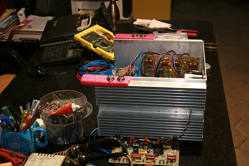
Building a 300 watt Hi-fi power amp, which we designed and prototyped few years ago. Please follow the links for details.
http://www.diyaudio.com/forums/solid-state/10387-310w-power-amplifier.html
http://www.diyaudio.com/forums/solid-state/10387-310w-power-amplifier-4.html#post1330047
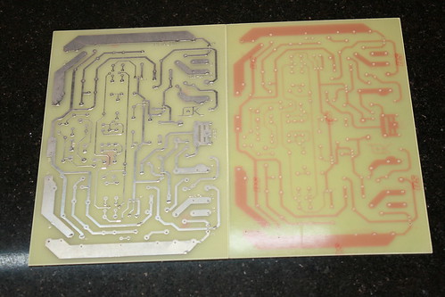
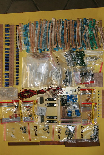
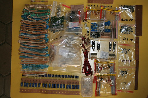
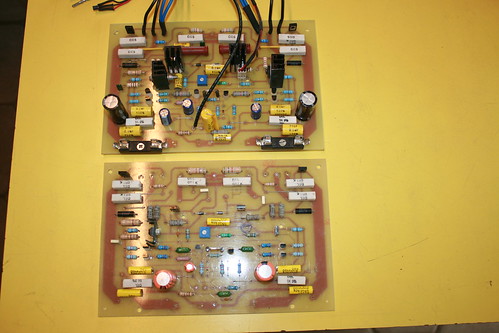
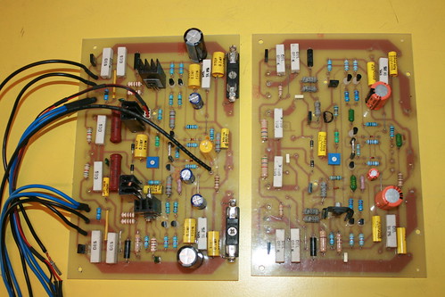
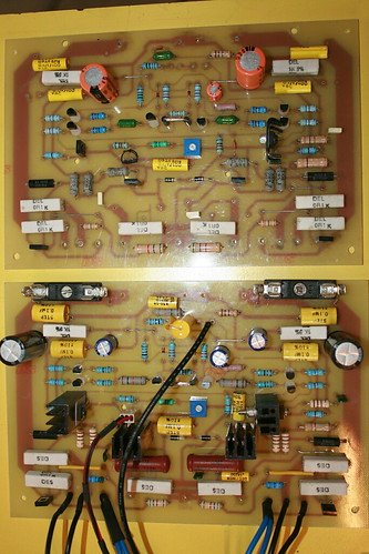
PCBs have been fabricated and gathering all components on hand.
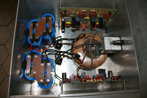
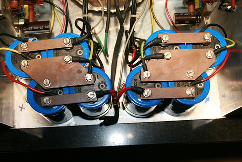
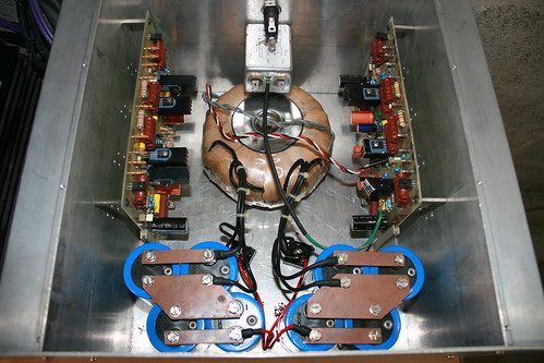
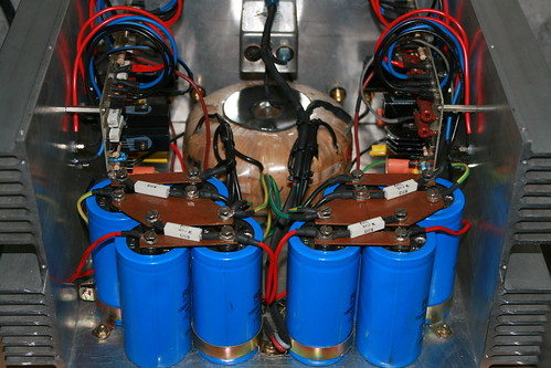
Few pictures of the same.
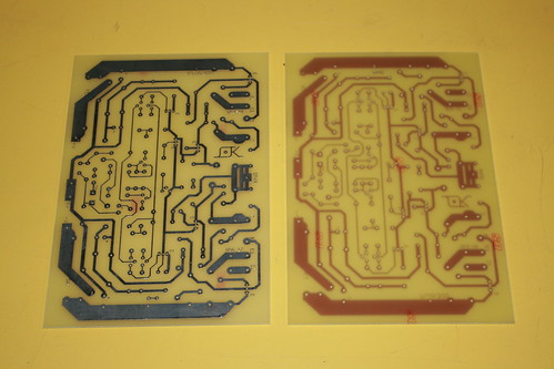
IMG_4459 by hydrovac, on Flickr
IMG_4458 by hydrovac, on Flickr
IMG_4461 by hydrovac, on Flickr
IMG_4462 by hydrovac, on Flickr
IMG_4570 by hydrovac, on Flickr
IMG_4575 by hydrovac, on Flickr
IMG_4465 by hydrovac, on Flickr
IMG_4464 by hydrovac, on Flickr
Building a 300 watt Hi-fi power amp, which we designed and prototyped few years ago. Please follow the links for details.
http://www.diyaudio.com/forums/solid-state/10387-310w-power-amplifier.html
http://www.diyaudio.com/forums/solid-state/10387-310w-power-amplifier-4.html#post1330047
PCBs have been fabricated and gathering all components on hand.
Few pictures of the same.
IMG_4459 by hydrovac, on Flickr
IMG_4458 by hydrovac, on Flickr
IMG_4461 by hydrovac, on Flickr
IMG_4462 by hydrovac, on Flickr
IMG_4570 by hydrovac, on Flickr
IMG_4575 by hydrovac, on Flickr
IMG_4465 by hydrovac, on Flickr
IMG_4464 by hydrovac, on Flickr
Hi Guys
The distortion is going to be higher than it should be without inserting another gain stage between the driver and the outputs. There should also be some compensation around the second stage VASs, or from their output to the feedback node.
Have fun
Kevin O'Connor
Hi Kevin O'Connor,
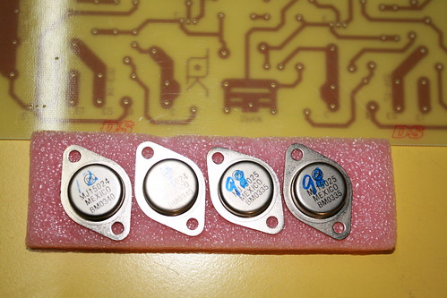
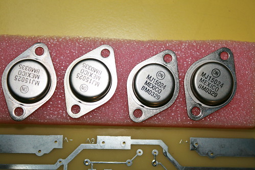
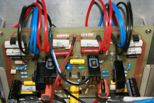
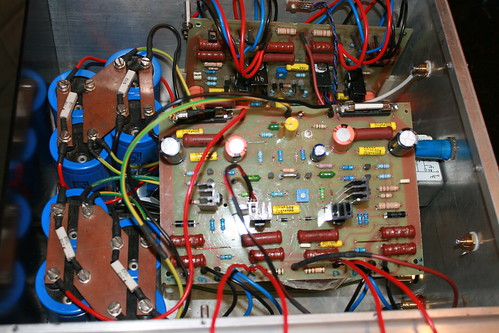
The amplifier can be divided into three separate parts. These are : the input stage, which consists of Q1-Q9 , a high gain, low power driver; the output or power stage- witch only has a voltage gain of four but enormous power gain; and the power supply. The input stage is a complementary -differential network, each ''side'' with its own current source. Each transistor in this stage is run at a collector currant of about 0.7mA. Emitter resistors are employed to stabilize the gain and improve linearity. The output of Q1-Q5 drives Q7 and Q9. The latter are virtually two constant-current sources run about 7mA collector current. With an input signal these ''current'' sources are modulated out of phase - the collector current of one decreases while the other increases. This configuration provides quite an amount of gain. In between the bases of these two transistors is Q8, the thermal sensing-bias transistor. The voltage across Q8 may be adjusted by TR1, thus setting the quiescent bias current for output stage. The output stage, Q10-Q11, Q13-Q14 and Q16-17, has a gain of about five, set by R44 and R28 plus R29. Diodes D4 and D6 prevent reverse biasing of Q10 and Q11 (otherwise the output would be limited). Protection of the output transistors is provided by Q12 and Q15 which monitor both current and voltage in the output transistors and bypass the base current if the limit is exceeded. Frequency stabilization provided by capacitors C6, C11, C12 and the RC networks R31/C10 plus R46/C15. Frequency response of the amplifier is set by C1 and C7 (lower limit), C6 sets the upper frequency limit.
Regards
krishna
Hi Guys
The distortion is going to be higher than it should be without inserting another gain stage between the driver and the outputs.
Kevin O'Connor
Kevin,
Please note that the output stage also has voltage gain!
John
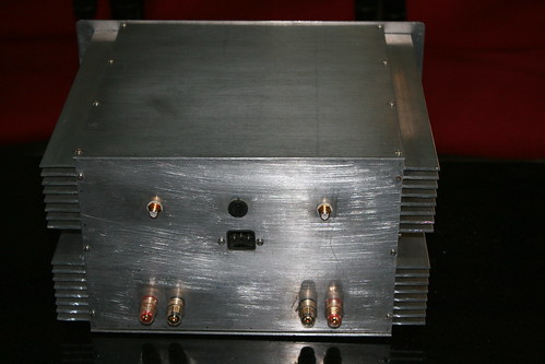
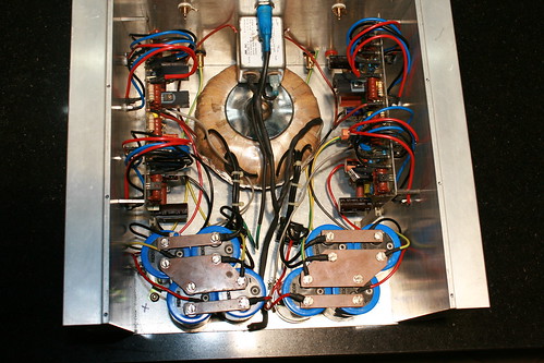
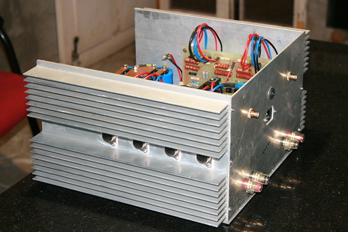
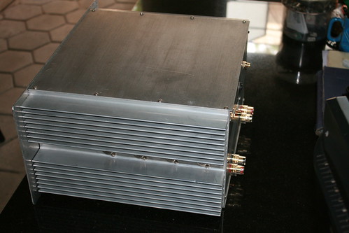
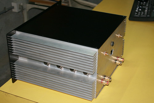
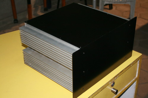
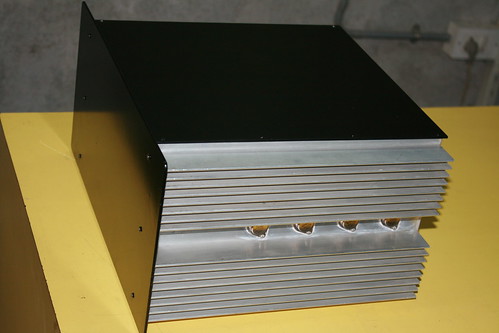
Holes for output devices drilled on heat sinks using a TO3 jig. Input and speaker binding posts holes done and connectors mounted.
IMG_4448 by hydrovac, on Flickr
IMG_4366 by hydrovac, on Flickr
IMG_4556 by hydrovac, on Flickr
IMG_4481 by hydrovac, on Flickr
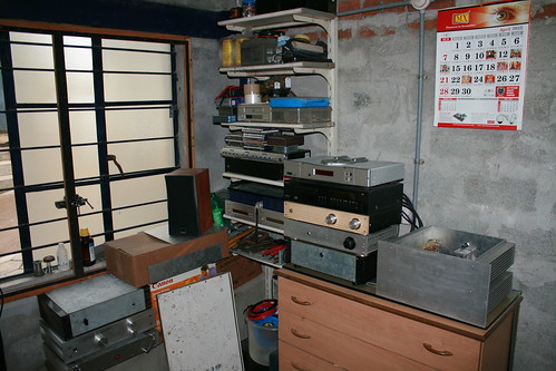
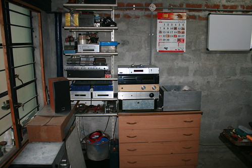
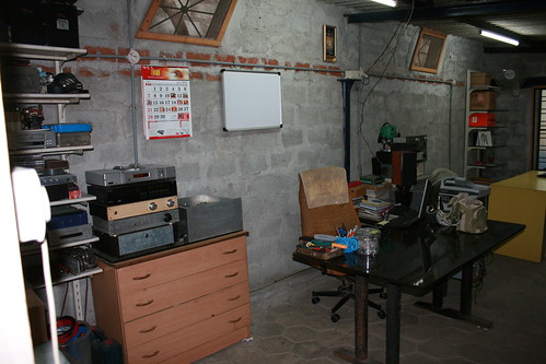
This is the den for our hobby & passion, and where all our classics come to life.
IMG_4399 by hydrovac, on Flickr
IMG_4398 by hydrovac, on Flickr
IMG_4397 by hydrovac, on Flickr
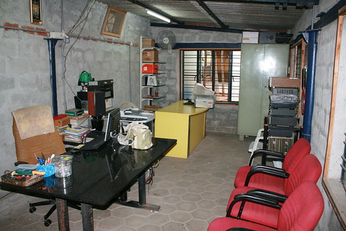
IMG_4396 by hydrovac, on Flickr
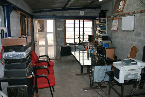
IMG_4315 by hydrovac, on Flickr
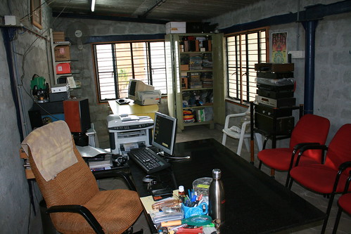
IMG_4314 by hydrovac, on Flickr
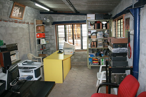
IMG_4313 by hydrovac, on Flickr
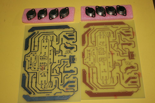
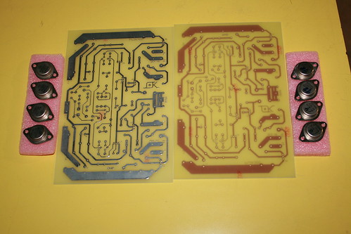
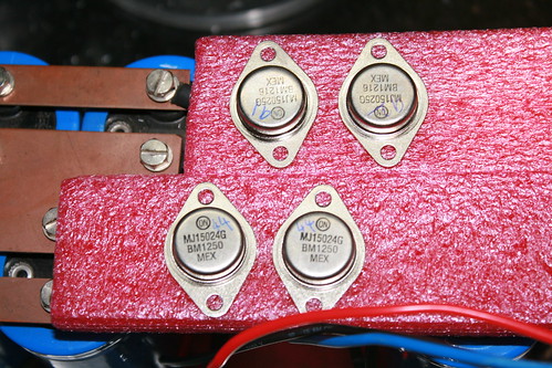
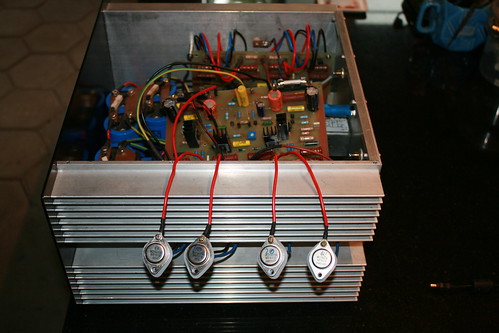
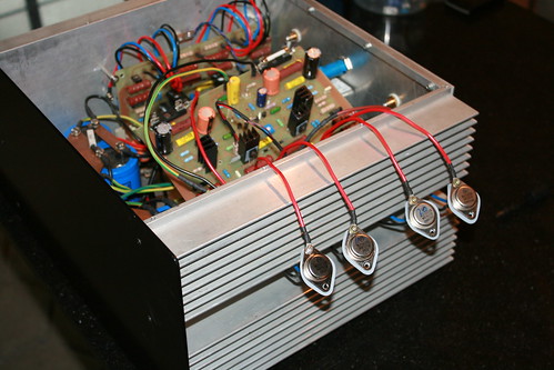
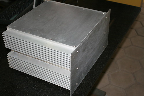
Power transistors mounting process and progress.
IMG_4420 by hydrovac, on Flickr
IMG_4412 by hydrovac, on Flickr
IMG_4409 by hydrovac, on Flickr
IMG_4416 by hydrovac, on Flickr
IMG_4414 by hydrovac, on Flickr
IMG_4412 by hydrovac, on Flickr
IMG_4449 by hydrovac, on Flickr
IMG_4442 by hydrovac, on Flickr
IMG_4448 by hydrovac, on Flickr
IMG_4366 by hydrovac, on Flickr
IMG_4556 by hydrovac, on Flickr
IMG_4481 by hydrovac, on Flickr
This is the den for our hobby & passion, and where all our classics come to life.
IMG_4399 by hydrovac, on Flickr
IMG_4398 by hydrovac, on Flickr
IMG_4397 by hydrovac, on Flickr
IMG_4396 by hydrovac, on Flickr
IMG_4315 by hydrovac, on Flickr
IMG_4314 by hydrovac, on Flickr
IMG_4313 by hydrovac, on Flickr
Power transistors mounting process and progress.
IMG_4420 by hydrovac, on Flickr
IMG_4412 by hydrovac, on Flickr
IMG_4409 by hydrovac, on Flickr
IMG_4416 by hydrovac, on Flickr
IMG_4414 by hydrovac, on Flickr
IMG_4412 by hydrovac, on Flickr
IMG_4449 by hydrovac, on Flickr
IMG_4442 by hydrovac, on Flickr
Hi Guys
You seem to be mistaking bandwidth limiting of input and feedback as compensation. They are two different things.
I am intimately familiar with this type of circuit, as it has been around since the early 1970s. There is no compensation in this circuit as the schematic is drawn. Instability occurs with reactive loads, and is visible on the scope as little bits of ringing - not to be confused with the output inductor's ringing with capacitive loads.
Good luck
Kevin O'Connor
its a very nice job for a DIY project ...though Cevin is right about a lot of things ...Listen to him he knows a few things more ...
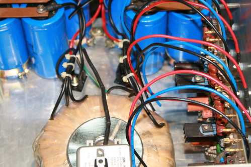
One of the things i hate is to see cans wired from boards ..If i ever made an amplifier with cans i will do it on a proper pcb never hard wired ....
Twisted hard wire will be twice as worst collector emitter will inject to base cable and then oscillation will be your closest friend ...
Seen an amp using flat cable not computer grade a click thicker with 6 leads for a pair of transistors ...you should see the scope readings : a complete Joke !!!
Kind regards
Sakis
Hi friends,
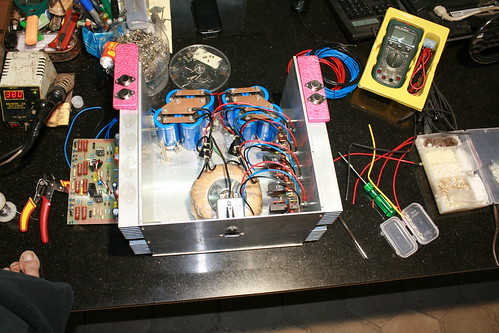
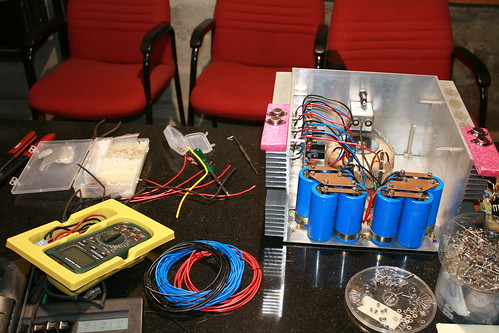
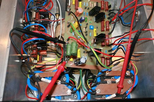
Sorry for the long gap in my post as I was preoccupied with other commitments. In continuation to my earlier posts, here is progress in amp build.
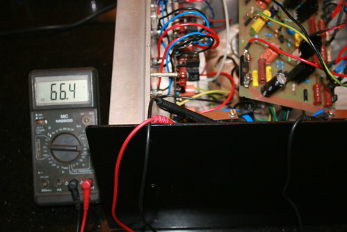
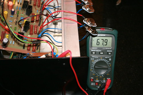
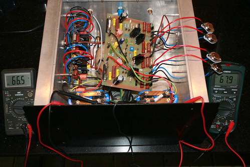
Checking the DC rail voltages: Left channel, Right channel, both channels
IMG_4645 by hydrovac, on Flickr
IMG_4646 by hydrovac, on Flickr
IMG_4648 by hydrovac, on Flickr
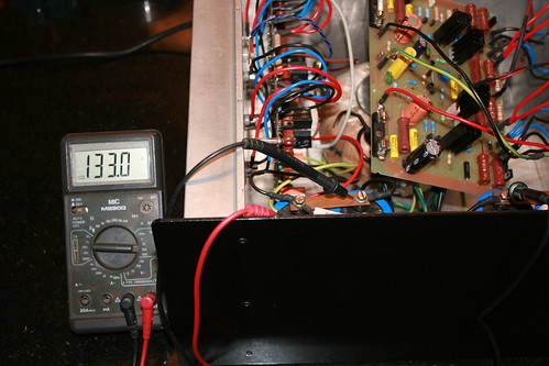
Checking full rail voltages: Left channel, Right channel, - Ve and +Ve rails
IMG_4652 by hydrovac, on Flickr
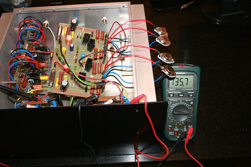
IMG_4653 by hydrovac, on Flickr
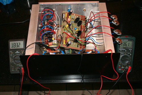
IMG_4655 by hydrovac, on Flickr
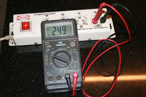
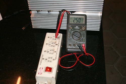
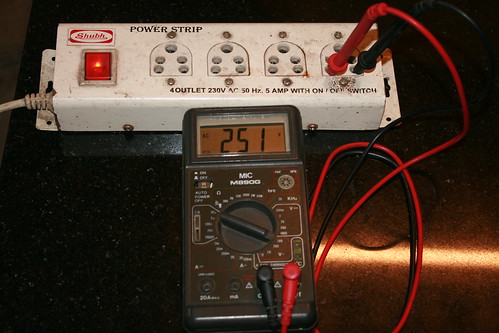
I am supposed to get around +62 and -62 volts DC on rails. The increase in reading is because of the mains input voltage (250 volts AC). Toroidal transformer winding is rated for 230 volts primary.
IMG_4682 by hydrovac, on Flickr
IMG_4686 by hydrovac, on Flickr
IMG_4683 by hydrovac, on Flickr
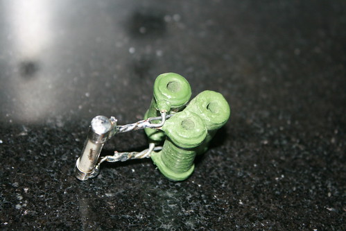
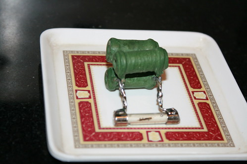
Setting the quiescent bias current for output stage:
Fabricated a 10 ohm 5 watt wire wound resistor suitable for the fuse holder.
IMG_4671 by hydrovac, on Flickr
IMG_4674 by hydrovac, on Flickr
Inserted in +Ve side holder and switched on the power. Adjusted the trim pot to get, 1.0 volt across the resistor.
IMG_4658 by hydrovac, on Flickr
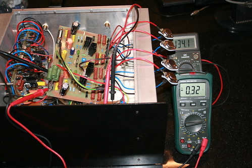
IMG_4660 by hydrovac, on Flickr
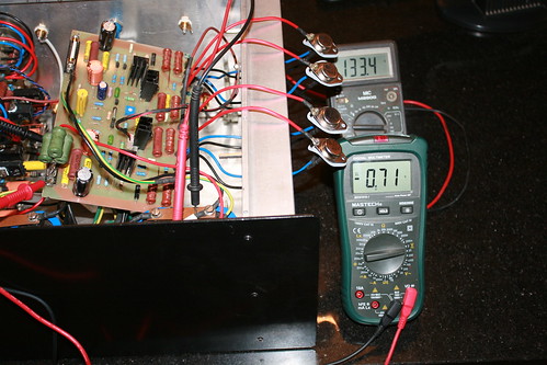
IMG_4661 by hydrovac, on Flickr
IMG_4662 by hydrovac, on Flickr
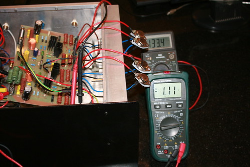
IMG_4657 by hydrovac, on Flickr
IMG_4659 by hydrovac, on Flickr
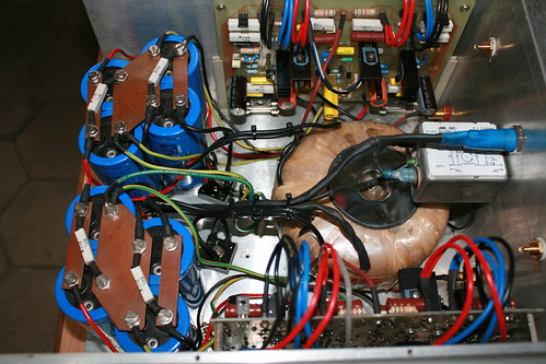
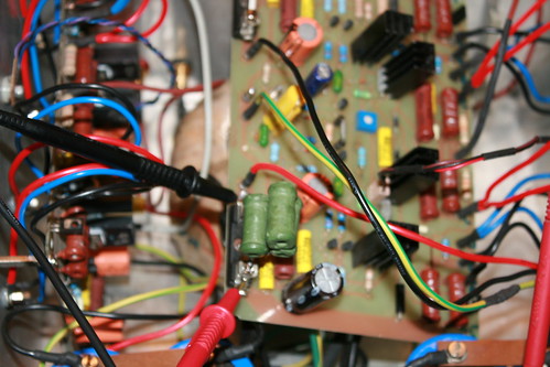
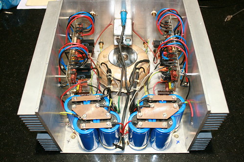
You can see the thermal sensing bias transistors mounted mid way between the power transistors on the heat sink. Good going so far.
IMG_4678 by hydrovac, on Flickr
IMG_4680 by hydrovac, on Flickr
IMG_4679 by hydrovac, on Flickr
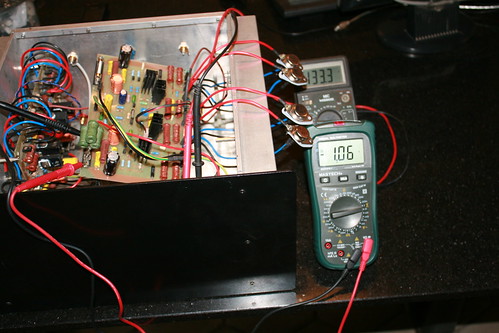
Now, looking at output side. Measuring the speaker output terminals for DC.
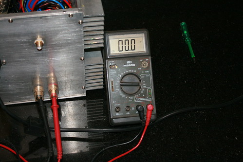
IMG_4669 by hydrovac, on Flickr
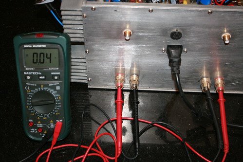
IMG_4668 by hydrovac, on Flickr
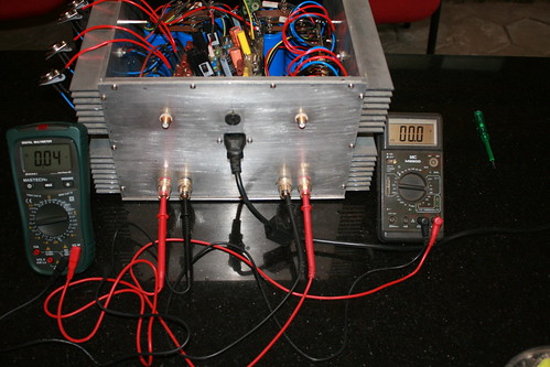
IMG_4667 by hydrovac, on Flickr
Left channel looks clean without any DC. But right channel is showing 0.04 volts. There seems to be a hitch somewhere. I will get back with updates after trouble shooting.
Thanks for looking and following the post.
Sorry for the long gap in my post as I was preoccupied with other commitments. In continuation to my earlier posts, here is progress in amp build.
Checking the DC rail voltages: Left channel, Right channel, both channels
IMG_4645 by hydrovac, on Flickr
IMG_4646 by hydrovac, on Flickr
IMG_4648 by hydrovac, on Flickr
Checking full rail voltages: Left channel, Right channel, - Ve and +Ve rails
IMG_4652 by hydrovac, on Flickr
IMG_4653 by hydrovac, on Flickr
IMG_4655 by hydrovac, on Flickr
I am supposed to get around +62 and -62 volts DC on rails. The increase in reading is because of the mains input voltage (250 volts AC). Toroidal transformer winding is rated for 230 volts primary.
IMG_4682 by hydrovac, on Flickr
IMG_4686 by hydrovac, on Flickr
IMG_4683 by hydrovac, on Flickr
Setting the quiescent bias current for output stage:
Fabricated a 10 ohm 5 watt wire wound resistor suitable for the fuse holder.
IMG_4671 by hydrovac, on Flickr
IMG_4674 by hydrovac, on Flickr
Inserted in +Ve side holder and switched on the power. Adjusted the trim pot to get, 1.0 volt across the resistor.
IMG_4658 by hydrovac, on Flickr
IMG_4660 by hydrovac, on Flickr
IMG_4661 by hydrovac, on Flickr
IMG_4662 by hydrovac, on Flickr
IMG_4657 by hydrovac, on Flickr
IMG_4659 by hydrovac, on Flickr
You can see the thermal sensing bias transistors mounted mid way between the power transistors on the heat sink. Good going so far.
IMG_4678 by hydrovac, on Flickr
IMG_4680 by hydrovac, on Flickr
IMG_4679 by hydrovac, on Flickr
Now, looking at output side. Measuring the speaker output terminals for DC.
IMG_4669 by hydrovac, on Flickr
IMG_4668 by hydrovac, on Flickr
IMG_4667 by hydrovac, on Flickr
Left channel looks clean without any DC. But right channel is showing 0.04 volts. There seems to be a hitch somewhere. I will get back with updates after trouble shooting.
Thanks for looking and following the post.
Actually 40mv dc offset isn’t that bad. I traced it to a slightly leaky cap. Replaced it and now it reads 1.5mv on right channel and 2.8mv on left channel, in 200mv range of multi meter.
My Dc offset is excellent and will not damage the speakers, but many say as high as 50mv is still OK.
I connected a source and performed an extensive listening session. Must confess the amp has an amazing sonic quality.
IMG_4441 by hydrovac, on Flickr
IMG_4445 by hydrovac, on Flickr
IMG_4478 by hydrovac, on Flickr
IMG_4482 by hydrovac, on Flickr
IMG_4580 by hydrovac, on Flickr
IMG_4579 by hydrovac, on Flickr
IMG_4577 by hydrovac, on Flickr
Have few extra PCBs to spare....
Have few extra PCBs to spare....
We would like to share our experience of the PWA 300 with other enthusiasts with passion for perfection. We designed this minimalist amplifier to be durable, simple to operate while offering high fidelity life like sound equivalent to the original source and would recommend partnering this amplifier only with other products of outstanding quality.
When we set out to design this amplifier, our aim was to create a product most suitable for the reproduction of complex music and speech signals. Although we placed high emphasis on electrical characteristics, the single most important requirement is achieving an audibly superior sound, vivid spatial imaging and superb tonal clarity. The low noise floor (no hum or noise) improved the dynamics and accuracy of the tonal characteristics of instruments and voices significantly.
Although the average listening level is normally less than 10 watts, our design approach was to create an amplifier with ample reserve power at average listening levels, reducing cross-over distortion to extremely low levels. The amp has almost zero phase distortion far beyond the audio range resulting in perfect resolution and totally UN-colored sound.
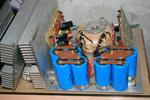
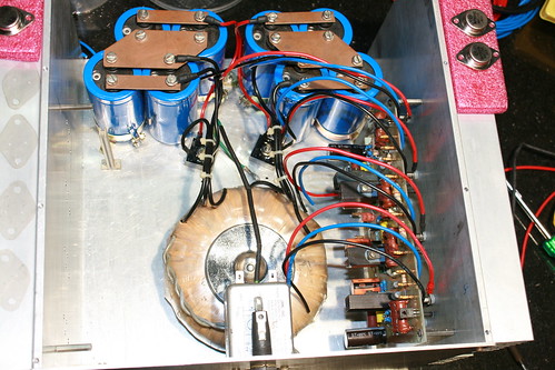
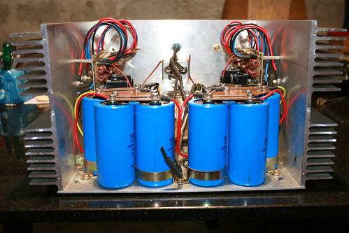
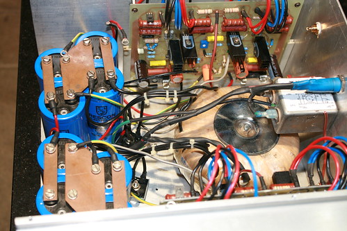
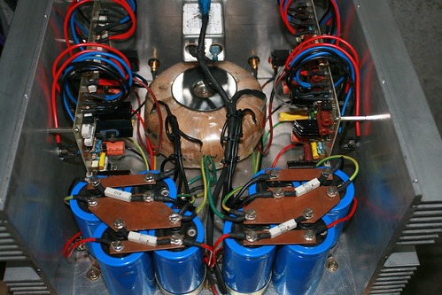
In order to obtain the full output power the supply transformer is rated at 45VAC – 0 – 45VAC at 375VA (each secondary) providing +/- 64VDC on rails. Unlike many designs relying on the reservoir capacitors to supply peak currents, we prefer to have the raw power available from the transformer resulting in much faster transients. The filter capacitor is around 40,000uF 100V for each rail.
Although the amps specifications are moderate, when listening to it you will immediately experience the massive reserve power available and never have any cause of anxiety that something is going to give in, that one would when driving many amplifiers loud.
You will hear nothing but reality with no distortion at any level and we guarantee that this amplifier will divulge the best qualities of the equipment connected to it. Of course speakers, inter-connections and source does play a significant role in the final result. However, the choice of speakers and music is like your choice of fine wine, it is what you enjoy.
I have few extra PCBs to spare and willing to assist any wannabe DIYer on the forum interested in building this power amp. I am convinced that you would be as pleased and proud owning this amplifier as I am, never finding the need to upgrade as it will provide you with many of years of listening pleasure. It sounds great and has had it on the signal generator and scope and output seems nice and flat all the way. We must say a word of thanks to Sam for putting this design on the net. The output devices mounting arrangement works very well and have added fan cooling that kicks in at 40 degrees.
Amplifier Specs:
Maximum Output: 200 watt rms into 8 Ohms, 300 watt rms into 4 Ohms
Audio Frequency Linearity: 20HZ - 20KHZ +/-0.5dB
Closed Loop Gain: 32 dB
Hum and Noise: -105 dB (input short circuit)
Damping Factor: 65 Output Offset Voltage: Less than 5 mV (input short circuit)
Phase Linearity: Less than 13 0 (10 Hz - 20 kHz)
Harmonic Distortion: Less than 0.007% at rated power
Distortion: Less than .009% at maximum power
Thanks for following the post and encouragement.
__________________
For some people, it's a part of life.
For others it's irrelevant.
The mysteries of neurology and how our individual brains function.
Have few extra PCBs to spare....
We would like to share our experience of the PWA 300 with other enthusiasts with passion for perfection. We designed this minimalist amplifier to be durable, simple to operate while offering high fidelity life like sound equivalent to the original source and would recommend partnering this amplifier only with other products of outstanding quality.
When we set out to design this amplifier, our aim was to create a product most suitable for the reproduction of complex music and speech signals. Although we placed high emphasis on electrical characteristics, the single most important requirement is achieving an audibly superior sound, vivid spatial imaging and superb tonal clarity. The low noise floor (no hum or noise) improved the dynamics and accuracy of the tonal characteristics of instruments and voices significantly.
Although the average listening level is normally less than 10 watts, our design approach was to create an amplifier with ample reserve power at average listening levels, reducing cross-over distortion to extremely low levels. The amp has almost zero phase distortion far beyond the audio range resulting in perfect resolution and totally UN-colored sound.
In order to obtain the full output power the supply transformer is rated at 45VAC – 0 – 45VAC at 375VA (each secondary) providing +/- 64VDC on rails. Unlike many designs relying on the reservoir capacitors to supply peak currents, we prefer to have the raw power available from the transformer resulting in much faster transients. The filter capacitor is around 40,000uF 100V for each rail.
Although the amps specifications are moderate, when listening to it you will immediately experience the massive reserve power available and never have any cause of anxiety that something is going to give in, that one would when driving many amplifiers loud.
You will hear nothing but reality with no distortion at any level and we guarantee that this amplifier will divulge the best qualities of the equipment connected to it. Of course speakers, inter-connections and source does play a significant role in the final result. However, the choice of speakers and music is like your choice of fine wine, it is what you enjoy.
I have few extra PCBs to spare and willing to assist any wannabe DIYer on the forum interested in building this power amp. I am convinced that you would be as pleased and proud owning this amplifier as I am, never finding the need to upgrade as it will provide you with many of years of listening pleasure. It sounds great and has had it on the signal generator and scope and output seems nice and flat all the way. We must say a word of thanks to Sam for putting this design on the net. The output devices mounting arrangement works very well and have added fan cooling that kicks in at 40 degrees.
Amplifier Specs:
Maximum Output: 200 watt rms into 8 Ohms, 300 watt rms into 4 Ohms
Audio Frequency Linearity: 20HZ - 20KHZ +/-0.5dB
Closed Loop Gain: 32 dB
Hum and Noise: -105 dB (input short circuit)
Damping Factor: 65 Output Offset Voltage: Less than 5 mV (input short circuit)
Phase Linearity: Less than 13 0 (10 Hz - 20 kHz)
Harmonic Distortion: Less than 0.007% at rated power
Distortion: Less than .009% at maximum power
Thanks for following the post and encouragement.
__________________
For some people, it's a part of life.
For others it's irrelevant.
The mysteries of neurology and how our individual brains function.
The current for the..........In order to obtain the full output power the supply transformer is rated at 45VAC – 0 – 45VAC at 375VA (each secondary) providing +/- 64VDC on rails. Unlike many designs relying on the reservoir capacitors to supply peak currents, we prefer to have the raw power available from the transformer resulting in much faster transients. The filter capacitor is around 40,000uF 100V for each rail...........
comes from the decoupling capacitors, not from the transformer.faster transients
The rectifiers ensure that the transformer is very effectively disconnected from the supply rails for something of the order of 80% of the time that the amplifier is operating.
The transformer DOES NOT supply the transient current to the speaker.
The transformer's job is to recharge the smoothing capacitors.
This design was first published in Electronic To Day International (ETI) 20 years ago. I most probably have the original article somewhere. The power and design interested me and i decided to buit it. Well it is still working after so many years the only upgrade is a regulated power supply with slightly reduced supply voltages of +/-65 v.Will take and attach a photo of the completed amp sometime this weekend. It is a very good sounding amp, highly recommended.
- Status
- This old topic is closed. If you want to reopen this topic, contact a moderator using the "Report Post" button.
- Home
- Amplifiers
- Solid State
- 300 watt Hi-fi power amp project.