Member
Joined 2009
Paid Member
Oh, I see. Well there may not be much available here. The GB150 schematic was released but not much else. You probably have to buy the amp from Greg or hook up with somebody who's built it.
What settings do you need? The dc-offset should be tuned to within a few 10'smV and the idle current to about 150mA per rail - same as TGM7.
What settings do you need? The dc-offset should be tuned to within a few 10'smV and the idle current to about 150mA per rail - same as TGM7.
Member
Joined 2009
Paid Member
back to the topic of speaker protection, I'm thinking of another crazy scheme!
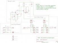
This time, something that I can pop into the power supply without needing to wire things up to the amplifiers. The idea is to look for a dc error and cut off the power rails. Instead of measuring a dc error at the amplifier outputs I would instead, look for the error in the speaker return current to the transformer/filter capacitor ground. It seems to check out OK in spice. I've 'borrowed' the basic circuit from the TGM8 amplifier protection circuit.
This time, something that I can pop into the power supply without needing to wire things up to the amplifiers. The idea is to look for a dc error and cut off the power rails. Instead of measuring a dc error at the amplifier outputs I would instead, look for the error in the speaker return current to the transformer/filter capacitor ground. It seems to check out OK in spice. I've 'borrowed' the basic circuit from the TGM8 amplifier protection circuit.
Attachments
Member
Joined 2009
Paid Member
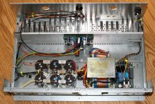
This is the final version of the TGM7 amplifier.
I decided to go with a mono-block, so that I had lots of headroom on the power supply and heatsink, plus the wiring is easier (back panel has cut outs for total 3 channels for future expansion). The power rails measure at just over +/-52V at idle. Bias is set around 120mA per rail (could probably be set quite a bit higher if warranted).
I think I described the power supply already - soft start module included, trafo then feeds a snubbered bridge rectifier and then 3 pairs of 10,000uF 63V caps in a C-R-C-R-C topology. The speaker return, input RCA ground, amplifier ground and safety earth (back to back diodes to chassis) all terminate at star ground between the final caps. Chasis is connected to IEC ground pin.
For speaker protection I decided on an 800R 5W resistor between the CT of the transformer secondary and the star ground. The amplifier has fuses in the output, inside the feedback loop (see earlier details).
Attachments
Bigun
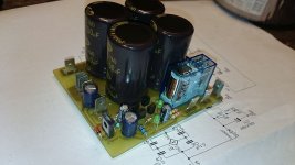
I am using simple speaker protection circuit, it is working very well, for past few yeares never failed me down. It may be usefull for you.
The time can be adjusted simple by changing one capacitor value. The 12V and 24V relays can be used (just one zener replacement neaded if required). There is no neaded additional supply either.
-DC protect
-delay speaker ON
-fast speaker OFF (when transformer is switched OFF)
Movie:
https://www.youtube.com/watch?v=lC-piRLDKzc
And few pics bellow.
Happy New Year!!
Attachments
Member
Joined 2009
Paid Member
Hi Andrew, yes that is a belly strap. I think they are a good idea. I didn't add this one, as AJT correctly identified this is a Japanese trafo recycled from a Pioneer HT 7 ch receiver. It's a sturdy unit although I wouldn't have wanted to use it for multiple channels it provides plenty of grunt for this mono block. The heatsink came out of the same HT unit and was transplanted into anold Fisher chasis ( which I modified ). I do believe that old HT receivers represent a huge opportunity for scrounging DIY transformers and heatsinks.
Borys, I decided not to use anything fancy for this build even though I have a protection unit off eBay somewhere. I've been struggling to do any hands on DIY for a year now due to family comittmemts and wanted to keep the effort to a bare minimum. The TGM7 does not need any turn on / off thump protection, with the soft start it's silent as a mouse!
Borys, I decided not to use anything fancy for this build even though I have a protection unit off eBay somewhere. I've been struggling to do any hands on DIY for a year now due to family comittmemts and wanted to keep the effort to a bare minimum. The TGM7 does not need any turn on / off thump protection, with the soft start it's silent as a mouse!
Last edited:
Hi Bigun,
Congratulations on your beautifull build!��
Could you please post a detailed comparision of the sound between the TGM7 and the TGM8? Bass, mids (i'm very courious about mids)' highs, soundstage, level of detail, perceived "speed" of the sound, etc...
Thank you and a Happy New Year!��
Congratulations on your beautifull build!��
Could you please post a detailed comparision of the sound between the TGM7 and the TGM8? Bass, mids (i'm very courious about mids)' highs, soundstage, level of detail, perceived "speed" of the sound, etc...
Thank you and a Happy New Year!��
Nice work,please post the pcb pdfBigun
I am using simple speaker protection circuit, it is working very well, for past few yeares never failed me down. It may be usefull for you.
The time can be adjusted simple by changing one capacitor value. The 12V and 24V relays can be used (just one zener replacement neaded if required). There is no neaded additional supply either.
-DC protect
-delay speaker ON
-fast speaker OFF (when transformer is switched OFF)
Movie:
https://www.youtube.com/watch?v=lC-piRLDKzc
And few pics bellow.
Happy New Year!!
")
Member
Joined 2009
Paid Member
I've been using this TGM7 amp as my main amp for the past few weeks again. Very nice amplifier, clean, no sign of harshness or fatigue - simply honest.
The volume pot failed this morning - a cheapo unit recovered from an old Sansui amp. Had to temporarily insert my trusty tube amp into the system. It's my first ever builud of a tube amp, a 6AS7 based SET called 'Cellini' (on the valves forum). It was not a step up today, sounds somehow deficient, less bass, the mids are not quite right - just 'less' all over. I'll be scrapping my tube amp and building something else with the parts based on this experience.
The volume pot failed this morning - a cheapo unit recovered from an old Sansui amp. Had to temporarily insert my trusty tube amp into the system. It's my first ever builud of a tube amp, a 6AS7 based SET called 'Cellini' (on the valves forum). It was not a step up today, sounds somehow deficient, less bass, the mids are not quite right - just 'less' all over. I'll be scrapping my tube amp and building something else with the parts based on this experience.
Member
Joined 2009
Paid Member
Somebody just asked me (via PM) what value I had settled on for R26. I just took the lid off and checked. I settled on 18k for the final value of R26.
One edit I haven't tried, is the value of the LTP degeneration resistors. I found a post from Mike ('mikelm') almost exactly 7 years ago where he said that his build of the SKA amp 'came alive' once the degeneration was removed.
One edit I haven't tried, is the value of the LTP degeneration resistors. I found a post from Mike ('mikelm') almost exactly 7 years ago where he said that his build of the SKA amp 'came alive' once the degeneration was removed.
Last edited:
TGM7 in 2018 - ska-audio site offline
Hi Bigun, reading those kind of threads is like following a detective series. I just feel the tension going about upper frequency oscillations seeing you identifying and fixing it.
I've bought a monster kit from Greg late 2014 for a bi-amping project (4x amps), but finally burned all amps due to lack of skills and /or broken components. A true nightmare for the audiophile bankrupt!
Question - will I never get my SKA amps running, especially since Greg’s site is down for quite a while? Life isn’t worth living…
So what’s the last word for TGM7? V2? Any pcbs in stock since? I've seen the BOM and other stuff, but I'd love to have a build guide or smth. Maybe I'm the one who writes a great one, from the lamer point of view to bring great electronics to the masses
Also which version to go for? CFA, VFA? And how to build them differently?? Man, I can’t tell how I'm eager to move this forward a bit, so seeing your last post in 2018 keeps me motivated realizing the SKA GB150D is alive as well as Mr. Balls heritage.
Many thanks and by best regards,
fench
Member
Joined 2009
Paid Member
Hi Fench,
sorry - no boards left, but to be perfectly honest it's cheaper to download the gerbers that I posted in this thread and order your own directly from China, rather than pay me to sort it all out.
I would stick with the VFA. There was a time when there was a lot of hype about CFA vs VFA. It was all a complete load of tosh. Designed properly they are both capable of equal performance.
Can't advice Re: your official amps - I stopped paying any attention to Greg and his stuff due to some strange behaviour on his forum. I hope he's in good health.
Hi Bigun, reading those kind of threads is like following a detective series. I just feel the tension going about upper frequency oscillations seeing you identifying and fixing it.
I've bought a monster kit from Greg late 2014 for a bi-amping project (4x amps), but finally burned all amps due to lack of skills and /or broken components. A true nightmare for the audiophile bankrupt!
Question - will I never get my SKA amps running, especially since Greg’s site is down for quite a while? Life isn’t worth living…
So what’s the last word for TGM7? V2? Any pcbs in stock since? I've seen the BOM and other stuff, but I'd love to have a build guide or smth. Maybe I'm the one who writes a great one, from the lamer point of view to bring great electronics to the masses
Also which version to go for? CFA, VFA? And how to build them differently?? Man, I can’t tell how I'm eager to move this forward a bit, so seeing your last post in 2018 keeps me motivated realizing the SKA GB150D is alive as well as Mr. Balls heritage.
Many thanks and by best regards,
fench
Hi fench,
You can bay finished amp VFA boards from me here, not Greg design but mine: ThermalTrak amplifier boards
Damir
Member
Joined 2009
Paid Member
My first response would be TGM8. Of all my amplifiers, DIY and commercial, it is hands down the best I have heard because it gets all three right - tight powerful bass, clear tube-like highs and an impeachable mid range. But it's been a few years since I have listened to my TGM8 or my TGM7 and it would be good at some point to go back and listen to both of them again. The TGM7 has some advantages - it's all FET so theoretically more robust as FETs do not suffer from secondary breakdown in the way that BJTs do (however TGM8 is an unusual design and under stress it presents FETs at the output, only at low signal does it present BJT at the output), the TGM7 is a simpler build, the pcb does not include dc output protection and so it's cleaner, it has no input or output capacitor and since it is based on the GB150 it is a design proven reliable over many years by many builders whereas the TGM8 is a unique design of mine which has not the same pedigree of field testing.
Hi Bigun,
Thanks for reply. I've checked your BOM TGM7 Files.zip and got my explaination about the differences in CFA vs. VFA. Quite self-explainatory - great!
I'm still wondering about how the amps should look like when finally build. Where do I place the MOSFETs, where to mount on heatsink. Where to place the bias temp regulator stuff on heatsink etc. These questions belong to a proper build thread I guess, but would be great if any could post some images (also wiring schemes, psu etc.)
I remember Greg insisted on matched pairs for both, the MOSFETS and the
BC556 / BC546. Is that true for the TGM7?
Also greg did had a more ballsy version, the GB300D with 6 MOSFETS. How much effort it would be to expand the TGM7 toward this?
Hi
dadod,
Thanks, only interested in Gregs based stuff.
Member
Joined 2009
Paid Member
Hi Fench,
I don't think you need to go to 6 FETs unless you have a nasty speaker to drive, i.e. low impedance (say 2 Ohm). In my opinion, the difference between 150W and 300W ain't worth worrying - the difference in loudness isn't enough to make a big difference but that's your call. It might be quite easy to expand TGM7, but that would be a project for you and not for me
Matching - yes, you want to match the MOSFETs. For the smaller devices, it's traditional to match the LTP devices. But Greg's amp is unusual, it doesn't operate the LTPs in very good balance. This doesn't matter because the resulting 2nd harmonic cancels at the output stage on account of there being two LTPs set up in a complementary fashion. I see little value in matching the LTP devices. However, since my TGM7 is very much based on Greg's design, you may opt to follow his advice and there would be no argument from me.
As for some photos - there should be some in this thread (the one's I posted in his forum were deleted by Greg), look at post #160 in particular. I will offer the following advice:
a) install all the small bits first and clean the flux off after soldering
b) for the TO-126 style transistors on the back of the pcb, install them first with bolts in place through the pcb so that they are aligned nicely, then solder them in. The two nearest the centre are not part of the circuit, they are there only as spacers for the power FETs and you'll need to trim their legs off except the centre one which you cut short and bend down to the surface of the pcb - soldering it to a dummy pad secures it from falling off (alternatively, just cut all the legs off and glue them to the underside of the pcb).
c) for the power FETs, bend the leads to the right shape and bolt the pcb through the FETs into the heatsink, you can put a smear of heatsink compound/grease on the outside pair of TO-126 devices before fitting the power FETs - this is helpful because these transistors act as temperature sensors for the power FETs mounted on top of them. This approach ensure the FETs are aligned properly, that they are flat and parallel to the heatsink before you solder their leads and it encourages them to stay that way even when you remove the assembly from the heatsink. I learned the hard way that any other approach is asking for lots of hassle or that the FETs won't be well aligned or that their leads will be stressed when bolted down. Avoid that by soldering them only with the assembly bolted down onto the heatsink.
Check really carefully before you solder in transistors and FETs that you have the right one's in the right places with the right orientation - with 3 legs they are difficult to remove so be prepared that if you get it wrong you have to cut them loose. Same goes for the SMD resistors - it requires you heat both ends at the same time to remove them, easy with two soldering irons, just about impossible otherwise.
If you have DIY'd in the past you probably know what precautions you want to take before and during first power-up. One thing to do is keep wiring tidy, keep output away from input, a messy bench can result in oscillations with a fast amp like this.
Last edited:
- Home
- Amplifiers
- Solid State
- TGM7 - an amplifier based on Greg Ball SKA