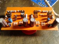
Namec 1000 watt
You can find it here,
https://www.facebook.com/groups/294726640658173/
but this is a closed group
You can find it here,
https://www.facebook.com/groups/294726640658173/
but this is a closed group
Attachments
Last edited:
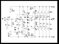
I don't want to say anything bad about someone's design. But there are many potential problems in this design...not an exhaustive list by any means
1. 50 Volt caps on 65 volt rails
2.TR4 current source has no power supply rejection
3. no hi-freq input filter
4. really high closed loop gain of about 214
5. C3 R6 corner is only 15 Hz (causes LF distortion)
6. R9 and R10 kind of high to drive so many output transistors
7. output stage is probably under-biased
8. no hf bypassing on the rails.
9. 2.2 mA in TR4 probably not enough to drive the kind of output currents you seek
10. Input biasing guarantees unbalanced first stage.
11. output power statements kind of optimistic
That's enough for now...although the phase inverter could probably use a lot of work also.
- Status
- This old topic is closed. If you want to reopen this topic, contact a moderator using the "Report Post" button.