Hello all.
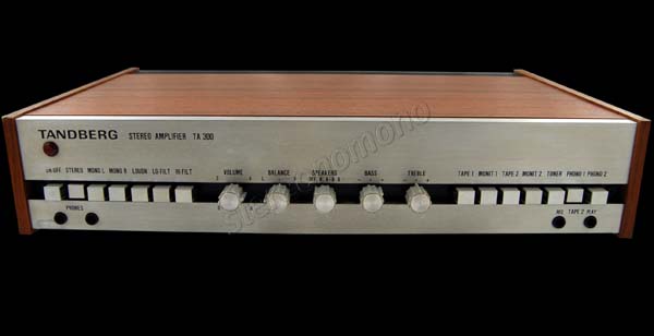
This is my first post, so hi everyone. My name is Kyrre and I'm a Norwegian musician, and seeing that all my music is to some extent based on the music that I listen to and how that sound affects me I figured it was time to up my game in the listening department. So I got a hand-me-down Tandberg TA 300 from my uncle that needed some work.
The left channel wasn't passing sound when I got it. I changed all the electrolytic capacitors into new ones, and then, the newbie that I was/am, I figured I'd just fire it up quickly to see if it was passing sound before connecting the transistors to the heat sink. Bad mistake, and I fried a couple of output transistors. So I got new ones and put them in, and slowly got it back to a state where it was passing sound, and sounding quite alright, actually.
See here for a pdf of the schematic (2,2 megs), and here you have the service manual (20 megs)
Still there were some distortion when listening on low volume on certain frequencies (basically around 200 Hz), and I started fiddling with the quiescent current and the symmetrical clipping pot. I didn't particularly know what I was doing, so I figured that I should measure the quiescent current across the emitter resistors. So I placed one probe of my DMM on the leg of one resistor, and the other on the leg of another resistor. At first I set it to 13 mV like it says in the manual, but the noise were still there, so I set it to 26 mV (seeing that I was measuring across two 0,22 ohm resistors). This didn't get rid of the distortion.
I then sent a 1000 Hz sine wave into the amplifier from my computer via SuperCollider. I switched the speakers (Tandberg HiFi System 20 speakers with 4 ohm resistance) to off and pushed up the volume control to full (like it says in the manual, but it says that you should connect 4 ohm resistors across the outputs as a dummy load. It also says that you should connect an oscilloscope and adjust it to achieve symmetric clipping, but I didn't have one, and was just really curious to see what the reading were like. Stupid, I know.). This should measure 11,8 V at point 6 in the schematic (see the link above). Now, let me see if I've got this right: this should be in AC Voltage mode, right? I connect one probe to the chassis and the other I push against point 6 on the PCB. I got around 15 V on the left channel, but on the right channel I couldn't find any AC voltage. I turned the amp off again and trimmed the symmetric clipping pots further down to lower the voltage on the left channel, but when I turned it on again the fuse blew and a MJE 3055 got fried. I bought a new one on ebay and I'm waiting for it to arrive now.
Does anyone know what may be the problem? I'd be happy to take pictures and provide readings, of course, but at the moment, the amplifier is non-functional, seeing that it's missing an output transistor.
I fully expect, and deserve, to be ridiculed for all this extremely un-elegant treatment of the poor amplifier. I will make it up again to the amp by playing sweet music through it, I promise.
I'm very grateful for any help with this. Thanks in advance.