Hi,
I am experimenting with a current feedback amplifier. This amp is to be used in a lab setup for various uses. Driving XY stages, driving Lorentz actuators or for instance simply dissipating power in resistors.
Specs should be "acceptable". High-end is not required.
For starters, I used an example circuit from the ESP website;
Opamp Based Power Amp
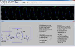
After minor adjustments, I 'built' the amp in LT Spice. All seemed well, until I upped the input voltage at which the positive rail doesn't seem to keep up with the required output.
Since I like to tinker with electronics, but don't have any proper electronics education, I cannot figure out why and where it goes wrong.
I've attached a pic and the LT Spice model. Who will find my issue? Please take a look at the model and pic. I hope I simply made an error somewhere.
PS; a 'DC-offset + Attenuation stage' will be implemented later on.
I am experimenting with a current feedback amplifier. This amp is to be used in a lab setup for various uses. Driving XY stages, driving Lorentz actuators or for instance simply dissipating power in resistors.
Specs should be "acceptable". High-end is not required.
For starters, I used an example circuit from the ESP website;
Opamp Based Power Amp
After minor adjustments, I 'built' the amp in LT Spice. All seemed well, until I upped the input voltage at which the positive rail doesn't seem to keep up with the required output.
Since I like to tinker with electronics, but don't have any proper electronics education, I cannot figure out why and where it goes wrong.
I've attached a pic and the LT Spice model. Who will find my issue? Please take a look at the model and pic. I hope I simply made an error somewhere.
PS; a 'DC-offset + Attenuation stage' will be implemented later on.
Attachments
Last edited:
Split R2 and bootstrap it. It is only providing about 0.6mA drive to the output pair at peak V swing. If the multiplied current gain of the 139/195 pair is only 10,000 (not unreasonable), then you will reach the current limit that you are getting.
Add another diode or resistor to increase difference between base drive potential for the 139 / 140 transistor pair...what you have is operating in class C.
Add emitter resistors for 139 / 140 in output path...just above and below where the lines combine to go to C3/R3/L1 connection.
Why C1?
Add another diode or resistor to increase difference between base drive potential for the 139 / 140 transistor pair...what you have is operating in class C.
Add emitter resistors for 139 / 140 in output path...just above and below where the lines combine to go to C3/R3/L1 connection.
Why C1?
Hi Guys
Your simulated circuit is not at all like the Rod Elliot circuit you began with. His is just an opamp driving an output buffer with overall feedback - a composite or hybrid circuit with no current feedback in sight.
Opamp-based CFBs drive the output devices from the opamp supply rails, in the simplest form. The opamp must be given resistive load to work into so the supply current will vary and thus the voltages across the Rs in series with the supply pins will vary, giving the attached output devices something to amplify. An internal feedback loop is created between the output node of the whole circuit and that of the opamp by adding a resistor between these points. Global feedback is placed around the whole circuit.
More elaborate circuits have current mirrors in the supply leads of the opamp with the outputs of the mirrors driving an EF output stage. Again, the opamp needs a resistive load to work into, as above.
Discrete circuits are a lot faster. look at Linear technology's app note about composite amplifiers (app.21 from 1986). There are circuits with 3kV slew rates, and others that handle 125V signals. There are tonnes of CFB threads on this forum.
Have fun
Kevin O'Connor
- Status
- This old topic is closed. If you want to reopen this topic, contact a moderator using the "Report Post" button.