This thread is about my Enhancer circuit. Referencing other circuits/ideas etc is fine, but indepth discussions about them is OT.
It would helpful, & nice, if others could sim the Enhancer & experiment with different components, to post what they are able to do with it
Will do, & i'll post my results")
It would helpful, & nice, if others could sim the Enhancer & experiment with different components, to post what they are able to do with it
Originally Posted by Bonsai
I'd bandwidth limit the signal to your enhancer Zero D
Will do, & i'll post my results
and my last post was showing an important general principle of broad equivalence between various negative feedback circuits
the point being that any circuit distortion, input or output Z "improvement" then has to come from added loop gain by "conventional negative feedback", properly measured - with the possibility of adding a pre-filter to shape the response independent of the feedback
then some elaborate schemes that attract the eye, naive human heuristics like "error only amplification" are really just ways of adding loop gain and it becomes easier to recognize how much "improvement" and where the limits are - since they are exactly the limits of any negative loop feedback scheme
...Bode Integral relations are fundamental negative feedback limits, show the required trade-off for linear loop stability re gain/phase vs frequency
I try not to miss any chances to recommend BJ Lurie's work - although his books are hard to understand and "buggy" - needing 2nd editions but he really shows how to use Classical Control techniques - you can still view his old site with archive.org Dr. Boris J. Lurie's Homepage: Classical Feedback Control
one thing Lurie does really well is show that the “conservation” relation for the total amount of feedback - the “Bode Integral” is exactly such a practical "good theory" - and has been the underpinning fundamental argument behind my posts in this thread
http://trs-new.jpl.nasa.gov/dspace/bitstream/2014/19495/1/98-0905.pdf
...
@ Bonsai
I now see our circuits are very similar, so i appologise if you thought i was treading on your toes etc My circuit doesn't have the diodes in U2's feedback path though, & of course the component values are different.
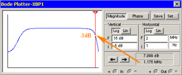
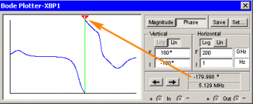
As you suggested, i've included a LPF filter @ the input = 100R & 2nf = 80kHz. The fr is still very extended, & THD is still 0.001% or less @ 1kHz, but the Phase looks problamatic.
I now see our circuits are very similar, so i appologise if you thought i was treading on your toes etc
My circuit doesn't have the diodes in U2's feedback path though, & of course the component values are different.As you suggested, i've included a LPF filter @ the input = 100R & 2nf = 80kHz. The fr is still very extended, & THD is still 0.001% or less @ 1kHz, but the Phase looks problamatic.
Attachments
Zero D,
The bode plotter on the right goes out to 200 GHz! Even with the usual simplified models accounting for parasitics (e.g. ESL and ESR in capacitors), you'll be lucky to get accurate results above about 50 to 200 MHz.
In any case, these look like closed-loop plots. These don't really tell you anything about stability.
and my last post was showing an important general principle of broad equivalence between various negative feedback circuits
Lest you feel under- or un- appreciated, I would like to say that I have greatly appreciated the posts you've made to this thread. Thank you.
Originally Posted by jcx
the point being that any circuit distortion, input or output Z "improvement" then has to come from added loop gain by "conventional negative feedback", properly measured - with the possibility of adding a pre-filter to shape the response independent of the feedback
Thanks, yes the input pre-filter does indeed help. And with it i am able to use much lower value Caps on U1 & U2 feedback resistors, whilst still retaining a very high bandwith & well behaved phase. The HB sims i'm doing are just out of curiosity, & naturally i wouldn't expect an actual design to fly so high.
Originally Posted by HarryDymond
The bode plotter on the right goes out to 200 GHz!
Hi, yeah i kept expanding the plot to view as much detail as it was able to present. I just thought it looked interesting what "appears" to happen Way up there, in a sim anyway. You're right of course, in Actuality with real components etc, i wouldn't expect to see that, or suffer the consequences.
In any case, these look like closed-loop plots.
Yes they were.
These don't really tell you anything about stability.
Would the best way to establish that, to include the L & C you described etc via PM earlier ? Or ?
Originally Posted by Bonsai
for the input filter, you need to connect the enhancer input (I.e. reference) to the point after the main amplifier input filter and not filter it separately.
Have you planted a screen logger in my comp ?
Only kidding, i know you havn't, & anyway my Anti such software will stop it dead in it's tracks You're right though, i had forgot to connect the Enhancer input to the filter output ! So Thanks for the heads up If you filter separately, the the roll offs are not the same, you will likely get overshoot.
I've just corrected it, & i'm still getting similar excellent results as before, but this time no big phase shift way up high
Yes, if the input signal bandwidths to the main amp and the error amp are not the same you get problems. I would also recommend that you buffer the reference signal. The enhancer error amp clamp diode capacitance + the enhancer error amp comp cap modulate the input filter node if you dont buffer it, and that causes distortion. You may find in your particular iteration that the effect is very small, but in my effort (which was a power amp), it made an important difference (See Fig 3 on my write up).
Close Loop for stability?
I'm not trying to be argumentative .. just asking if you have encountered any situations whether 'real life' or sim where this is the case.
In the Closed Loop form of the Feedback Eqn, the Loop Gain 'models' the variable part of the Denominator. The traditional 'linear' measures show how close this gets to (-1,0). But this translates directly into peaking in the Closed Loop!
Of course stuff in the Numerator might mean the peaking appears somewhere down a HF slope but wonky stability should always show up.
This may not be provable analytically. In da past, I've vacillated between 'Yes it will show' and 'some crazy circuits may be wonky without showing up on Closed Loop'. But dis Millenium, I've firmly with Bob in suggesting that Closed Loop peaking will always accompany wonky stability, both in the main loop and any internal loops too.
Of course the traditional Loop Gain Bode, Nyquist, PM, GM are usually better if you are trying to improve stability.
_______________
There are 2 important practical reasons for confirming if this is true .. at least for Power Amps.
Of course, this is STILL a 'linear' measure of stability and won't show up stuff that's highly level dependent .. or even 'parasitics' and evil unknown semantically wonky 'excess phase'
Harry, do you have any evidence that an amplifier can have wonky stability without it clearly showing in the Closed Loop response .. either sim or 'real life'.In any case, these look like closed-loop plots. These don't really tell you anything about stability.
I'm not trying to be argumentative .. just asking if you have encountered any situations whether 'real life' or sim where this is the case.
In the Closed Loop form of the Feedback Eqn, the Loop Gain 'models' the variable part of the Denominator. The traditional 'linear' measures show how close this gets to (-1,0). But this translates directly into peaking in the Closed Loop!
Of course stuff in the Numerator might mean the peaking appears somewhere down a HF slope but wonky stability should always show up.
This may not be provable analytically. In da past, I've vacillated between 'Yes it will show' and 'some crazy circuits may be wonky without showing up on Closed Loop'. But dis Millenium, I've firmly with Bob in suggesting that Closed Loop peaking will always accompany wonky stability, both in the main loop and any internal loops too.
Of course the traditional Loop Gain Bode, Nyquist, PM, GM are usually better if you are trying to improve stability.
_______________
There are 2 important practical reasons for confirming if this is true .. at least for Power Amps.
- these days, with SPICE, it is trivial to do Closed Loop when in da old days, we would be wary of doing this in 'real life' .. in case the Holy Smoke escapes.
- much easier to measure 'real life' Closed Loop of an amp to zillion GHz than Loop Gain
Of course, this is STILL a 'linear' measure of stability and won't show up stuff that's highly level dependent .. or even 'parasitics' and evil unknown semantically wonky 'excess phase'
Last edited:
Harry, do you have any evidence that an amplifier can have wonky stability without it clearly showing in the Closed Loop response .. either sim or 'real life'.
I'm not trying to be argumentative .. just asking if you have encountered any situations whether 'real life' or sim where this is the case.
In the Closed Loop form of the Feedback Eqn, the Loop Gain 'models' the variable part of the Denominator. The traditional 'linear' measures show how close this gets to (-1,0). But this translates directly into peaking in the Closed Loop!
Of course stuff in the Numerator might mean the peaking appears somewhere down a HF slope but wonky stability should always show up.
This may not be provable analytically. In da past, I've vacillated between 'Yes it will show' and 'some crazy circuits may be wonky without showing up on Closed Loop'. But dis Millenium, I've firmly with Bob in suggesting that Closed Loop peaking will always accompany wonky stability, both in the main loop and any internal loops too.
Of course the traditional Loop Gain Bode, Nyquist, PM, GM are usually better if you are trying to improve stability.
_______________
There are 2 important practical reasons for confirming if this is true .. at least for Power Amps.
- these days, with SPICE, it is trivial to do Closed Loop when in da old days, we would be wary of doing this in 'real life' .. in case the Holy Smoke escapes.
- much easier to measure 'real life' Closed Loop of an amp to zillion GHz than Loop Gain
Of course, this is STILL a 'linear' measure of stability and won't show up stuff that's highly level dependent .. or even 'parasitics' and evil unknown semantically wonky 'excess phase'
These are all good points. I guess my statement was too sweeping. Closed-loop doesn't tell you nothing about stability: strange things (peaking) occurring in the closed-loop response would indeed ring alarm bells in terms of loop stability. However, I believe in this specific case the thing that Zero D was concerned about was not an issue (no peaking in the closed loop). It is better to just look at the loop gain plot.
I fully concur with your caution regarding relying solely on loop-gain plots, but I think that perhaps you go too far in the other direction poo-pooing the concept. Loop-gain plots are an extremely useful tool, and things like level-dependent circuit behaviour is why we need generous phase and gain margins in power amplifiers. Do not forget that it is possible to bias the amplifier to different operating conditions (e.g. with a stepped constant current source on the output) and to perform loop-gain plots at each step.
A time-domain method I like is superposing small square-wave steps onto a larger sinusoid and using this as the input signal to the amplifier. See the step-response to each edge change as the sinusoid varies in amplitude (don't forget to remove any bandwidth-limiting input filter!).
Of course the traditional Loop Gain Bode, Nyquist, PM, GM are usually better if you are trying to improve stability.
I don't really poo-poo the use of Loop Gain plots .. just suggesting that in SPICE world, Closed Loop plots are easy and worth looking at.... However, I believe in this specific case the thing that Zero D was concerned about was not an issue (no peaking in the closed loop). It is better to just look at the loop gain plot.
I fully concur with your caution regarding relying solely on loop-gain plots, but I think that perhaps you go too far in the other direction poo-pooing the concept. Loop-gain plots are an extremely useful tool, and things like level-dependent circuit behaviour is why we need generous phase and gain margins in power amplifiers.
as they show directly what we're concerned with.But when trying to tweak stability, I confess Loop Gain plots are my main tool though I like to use loadsa other tools too. Perhaps I should say ..
'Of course the traditional Loop Gain Bode, Nyquist, PM, GM are usually more useful if you are trying to improve stability.'
I agree that in Zero D's original context (matching the 'side' chain), Loop Gain is the useful view of the situation.
As a SPICE novice, I tend to use it like I would do 'real life' testing of power amps. Still trying to get to grips with the stuff it provides that have no 'real world' equivalent.
Last edited:
@ Bonsai
I tried it with the buffer, but for some reason the sim won't run with it ?
That's correct. By changing the values of the capacitors over the feedback resistors in the right ratios on U1 & U2, i can achieve a very high gain bandwith with no peaking etc. Lowering the bandwith is fine too.
Yes it was/is
I tried it with the buffer, but for some reason the sim won't run with it ?
Originally Posted by HarryDymond
However, I believe in this specific case the thing that Zero D was concerned about was not an issue (no peaking in the closed loop).
That's correct. By changing the values of the capacitors over the feedback resistors in the right ratios on U1 & U2, i can achieve a very high gain bandwith with no peaking etc. Lowering the bandwith is fine too.
Originally Posted by kgrlee
I agree that in Zero D's original context (matching the 'side' chain), Loop Gain is the useful view of the situation.
Yes it was/is
Can you enhance it?
I've got this: durable little kits upgraded like so: my new schematic in which case the gain divider is 27k vs 727r, and it is stable and the protections work, and even the tone is pretty. Those are good practical features, but there is one lack. . .
So, as you can see, it is still a chip amp and although this one is pleasant, it could make use of an upgrade in the imaging department. I've done a rather wide variety of experiments on it. It really takes quite the blunder to set off the protections, but twice I did find out that they work. So, experiments with this kit (after component value change to the new schematic for stability/durability especially) is "somewhat less likely" to cost output devices per each try.
Given that I have a PC source and those are dreadfully short of headroom, I really wouldn't want to decrease the power amp gain much on music; however, I've no objection to decreasing the gain on error.
Question:
Is the enhancer circuit made for literally decreasing the gain on error?
If so, that looks really useful!
@ danielwritesbac
Hi, & Thanks for your interest
My enhancer increases the Loop Gain & therefore bandwith, plus it reduces THD. What i wasn't aware of whilst i was designing/simming it, was Bonsai had a similar circuit http://www.diyaudio.com/forums/solid-state/225657-augmented-feedback-error-correction.html
So out of respect for him, i've gone quiet on mine, & wait to see how his pans out. I expect good things from it, & wish him All the best
Originally Posted by Bonsai
I've managed to get some loop gain plots done, but need to work through them a bit more before I put them up.
Keep us posted
I've had to use a 'simultaneous simulation' to get individual lots of the main amp loop gain and the AFEC loop.
Interesting, i wonder if that's why when i added the buffer it wouldn't run ?
- Status
- This old topic is closed. If you want to reopen this topic, contact a moderator using the "Report Post" button.
- Home
- Amplifiers
- Solid State
- THD & Loop Gain Enhancer