Hi
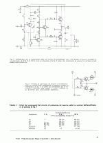
I've found this old amp circuit from Phillips, looking at the first image I don't see the output drivers transistors in the circuit, is it in the protection circuit in the lower part of the page in the image ?
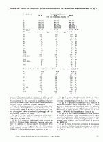
Btw, I find the value of C9 and C10 quite high.
Any opinions about this circuit ?
Thanx
Paul
Attachments
You don't see the drivers, because the output transistors are Darlington types as you can id. them in the parts list. Old school simple circuit, still it can be OK, but there are lots of newer, much better circuits out there. I don't really see the purpose of C9 and C10, maybe they are some kind of "accelerator" caps for the output devices (usually you can find one smaller value cap. between the two bases of the outputs, still their use is controversial according to experts)
Last edited:
Apparently the output transistors are darlingtons, they are just drawn as ordinary BJTs.
It's not impossible to build an amp without driver transistors. You can find complementary outputs with a beta near 200 and the VAS and boot strap load will have to burn several Watts. Don't expect ultra low distortion and a low output impedance.
It's not impossible to build an amp without driver transistors. You can find complementary outputs with a beta near 200 and the VAS and boot strap load will have to burn several Watts. Don't expect ultra low distortion and a low output impedance.
- Status
- This old topic is closed. If you want to reopen this topic, contact a moderator using the "Report Post" button.


