Dadod you should try sim the noise levels with the P1 used as a volume control, the results may not be that bad. Keep in mind that ODNF reduces not only distortion but also has a positive effect on noise.
How far are you into the development, this is a design Id like to build. I already have such a amp but with a simpler front end. I dont usually chase ultralow THD figures over simplicity but Id try this one out.
BTW I found my paperwork about the current mirror while I was doing my amps design a couple years back, I just have to put it into electronic form then Ill post it.
Dadod you should try sim the noise levels with the P1 used as a volume control, the results may not be that bad. Keep in mind that ODNF reduces not only distortion but also has a positive effect on noise.
How far are you into the development, this is a design Id like to build. I already have such a amp but with a simpler front end. I dont usually chase ultralow THD figures over simplicity but Id try this one out.
BTW I found my paperwork about the current mirror while I was doing my amps design a couple years back, I just have to put it into electronic form then Ill post it.
Manso, first I can't use P1 as a volume conntrol as ODNF as it's connected works with fixed gain. When P1 value is gonig down opamp acts more as a gain stage and whole amp as global negative feedback amp.
"Keep in mind that ODNF reduces not only distortion but also has a positive effect on noise."
It is written in the papers you mailed to me but I have problem with simulation.
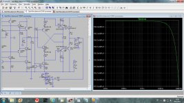
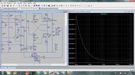
Below first picture shows noise with no ODNF active and second one is with ODNF active.
There is big difference in the noise level for worst with ODNF. It could be that LT opamp models are not good enough for this kind of simulatio. I am straggling to import Texsas Instruments opamp(LME49710 or LM4562) but no success yet.
Attachments
Here is my attempt to simulate a kind of ODNF but only acting on the output stage(gain bit lower then 1).
It is working with lower decrease in THD, but good enough. What I loose now is opmap acting as DC servo(becouse the gain stage could have some DC offset). Now I can use P1 as a volume control, but still opamp noise dominate, so what now?
Nex try with HEC OPS.
It is working with lower decrease in THD, but good enough. What I loose now is opmap acting as DC servo(becouse the gain stage could have some DC offset). Now I can use P1 as a volume control, but still opamp noise dominate, so what now?
Nex try with HEC OPS.
Attachments
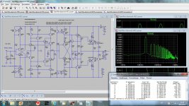
Yes I measured it, here is THD20k at the same output level I simulated whole amp.
which version of your circuit produces this sim?
Can you post/link .jpg or .asc file?
which version of your circuit produces this sim?
Can you post/link .jpg or .asc file?
That was the gain stage or current conveyor only with no OPS connected.
Hi Dadod
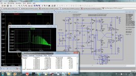
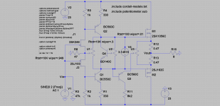
let me show the latest marks regarding odnf amp by Shinich Kamijo.
this amp uses a transistor instead of opamp in nfb.
the Vout signal is close from clipping.
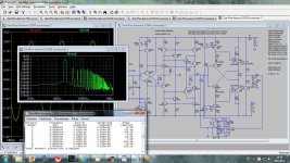
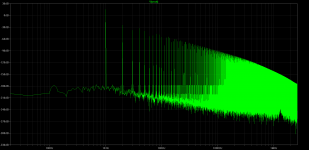
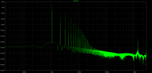
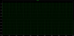
the first fft is with U3's wiper is set at 0.8, the second fft 0.01
As you can see main distortion are almost unchanged but look at hf hiss, it almost disapear!!!
let me show the latest marks regarding odnf amp by Shinich Kamijo.
this amp uses a transistor instead of opamp in nfb.
the Vout signal is close from clipping.
the first fft is with U3's wiper is set at 0.8, the second fft 0.01
As you can see main distortion are almost unchanged but look at hf hiss, it almost disapear!!!
Attachments
ups
you are right
but now ltspice got crazy
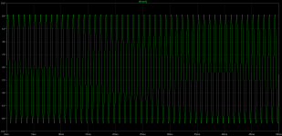
the probe at Vout shows -550mV
but on sinewave graph it is ~-12V...
asc attached
Interesting. Could you explain haw it should work?
@pawel
I found the lower side mosfet is Nch.
@dadad
this is the feedforward distortion cancellation based on 80's DENON's circuit, he wrote.
http://www.ne.jp/asahi/evo/amp/Dnfb/edc.htm
I reserched it ago and found a patent US4447790.
I found the lower side mosfet is Nch.
@dadad
this is the feedforward distortion cancellation based on 80's DENON's circuit, he wrote.
http://www.ne.jp/asahi/evo/amp/Dnfb/edc.htm
I reserched it ago and found a patent US4447790.
Attachments
Last edited:
@pawel
I found the lower side mosfet is Nch.
@dadad
this is the feedforward distortion cancellation based on 80's DENON's circuit, he wrote.
Distortion removal circuit
I reserched it ago and found a patent US4447790.
Thanks Shinja I will take a look at that.
@pawel
I found the lower side mosfet is Nch.
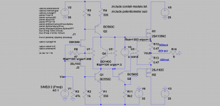
yes you are right again, this should be nmos too
this is cured circuit but not works as good as in post 27, the cancelation dost pot U3 not works... http://www.diyaudio.com/forums/solid-state/238252-odnf-no-gnfb-power-amp-3.html#post3542525
Attachments
Last edited:
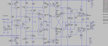
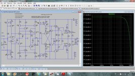
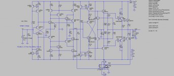
Nobody commented my implementation of the HEC output stage, it's a bit different from Hawksford.
Distortion decrease at 1kHz is 42dB and at 20kHz is 25dB.
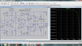
I simulated noise at full and at -40dB volume.
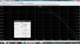
Next simulation is the gain.
As this amp is whitout GNFB output is not close enough to zero V, next step to add DC servo.
Distortion decrease at 1kHz is 42dB and at 20kHz is 25dB.
I simulated noise at full and at -40dB volume.
Next simulation is the gain.
As this amp is whitout GNFB output is not close enough to zero V, next step to add DC servo.
Attachments
Nobody commented my implementation of the HEC output stage, it's a bit different from Hawksford.
Distortion decrease at 1kHz is 42dB and at 20kHz is 25dB.
I simulated noise at full and at -40dB volume.
Next simulation is the gain.
As this amp is whitout GNFB output is not close enough to zero V, next step to add DC servo.
Dear Dadod
you know I like your designs very much and I am very impressed of their performance but I cannot compliment every post

Dear Dadod
you know I like your designs very much and I am very impressed of their performance but I cannot compliment every post
No compliments, technical comments only.
Dadod, that`s all nice in the simulation world but there`s a work ahead of you to therm. stabilize output stage and bias...
Bogdan, yes there is more work to do. Q31 and Q32 should be thermaly connected with output transistors and P2 used for the bias adjustment. D1 and D2 should compensate for ambient change of temperature. Those days I am occupied with my grandsons and less time left for audio hobby.
- Status
- This old topic is closed. If you want to reopen this topic, contact a moderator using the "Report Post" button.
- Home
- Amplifiers
- Solid State
- ODNF or no GNFB power amp