I've searched and read, and still can't find a definitive answer. I have an old receiver that uses a pair of BA312 opamps in the tone amplifier, one is dead. The supply is +35V. Supporting circuitry will have to be modified a bit, but I want to replace both opamps with a single OPA2604.
Am I going to have to build a zener +/- supply, or will the 2604 behave in a single supply environment?
Am I going to have to build a zener +/- supply, or will the 2604 behave in a single supply environment?
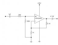
OK, I can see that with the low values of feedback resistors that low frequency rolloff with be too extreme unless cap size gets fairly large. Increase the resistors to the value here, and bump the cap size up a bit.
Sorry for what seems like stupid questions, but I honestly didn't know you could do this. If this works, it will save a lot of trouble.
Sorry for what seems like stupid questions, but I honestly didn't know you could do this. If this works, it will save a lot of trouble.
Attachments

Your input works only if your PS is quite, otherwise you will get noise and hum right in.
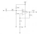
Better solution is:
2k2 + 2k2 creating half the voltage. From the junction down to ground 100 uF or so. From the junction 100 k to the + input
The caps is calculated f = 1/(2*pi*R*C) => 10 uF, 1 K => 16 Hz
Better solution is:
2k2 + 2k2 creating half the voltage. From the junction down to ground 100 uF or so. From the junction 100 k to the + input
The caps is calculated f = 1/(2*pi*R*C) => 10 uF, 1 K => 16 Hz
This is run off of a regulated supply that is well bypassed and is actually quite noise-free. Additionally, the circuit shown above lends itself quite well to the current component layout. Your suggestion would be excellent if there was room on the board, but component layout would become pretty cumbersome. I may try it next time if I can find the board space.peranders said:Your input works only if your PS is quite, otherwise you will get noise and hum right in.
Better solution is:
2k2 + 2k2 creating half the voltage. From the junction down to ground 100 uF or so. From the junction 100 k to the + input.
Which is why the resistors were upped to the values shown in the last schematic, and the cap increased to 47µf.The caps is calculated f = 1/(2*pi*R*C) => 10 uF, 1 K => 16 Hz
As it runs now, using 100MHz bandwidth on the scope, opamp output noise reads about 15mV P-P. Cut bandwidth to 20MHz, and noise reads about half of that. Sound quality is excellent, so I'm leaving good enough alone for now.
Thanks again for your help and comments. Being able to single-supply this opamp has saved me a lot of trouble.
Mind telling me how to accomplish that? Seems I would be shunting my signal to ground by adding a decoupling cap of any size large enough to make a difference.peranders said:I think it would be wise to decouple the noninverting input bias.
Me too. My scope won't measure that low. I measured about 8 millivolts P-P at the opamp output with a 20MHz bandwidth.I doubt that you have less noise and hum than 10 uV.
I think the language got on the way here. My post above is a statement rather than a question...was justYour last question: The resistor down to ground via the cap.
acknowledging that the cutoff for the RC filter on the feedback loop was too high with a 1K resistor and a 10µf cap. The other components were handy, and the frequency is lowered to a point where it is not an issue, so I put 'em in.
Still, I would be curious as to how you would propose to bypass. .01µf?
I could have gone that route if I didn't mind one old opamp for the one channel, and a nice new shiny  OPA604 for the other. However, I'd rather that the channels match as close as possible in gain and sound quality. The original opamps are mounted very close together, so replacing the original single channel jobs with a dual seemed to make good sense here.
OPA604 for the other. However, I'd rather that the channels match as close as possible in gain and sound quality. The original opamps are mounted very close together, so replacing the original single channel jobs with a dual seemed to make good sense here.- Status
- This old topic is closed. If you want to reopen this topic, contact a moderator using the "Report Post" button.
- Home
- Amplifiers
- Solid State
- OPA2604 on Single Supply...??