Fixed bias is super critical on the exact devices used. Best solution I think would be to replace R53 with a 1K preset and set the bias for around 15 mv (voltage across either 0.22 ohm)
Very dangeourous , even more for a newbie...
If the trimmer value is set to about 0 the iddle current
will climb to amperes values , best is to put this trimmer
in serial with a 270R resistor to limit the current range.
If the amp is functional then surely , and fortunately ,
that he connected the extreme sides only , hence
the non varying current when he trimed the pot...
You need to do a basic test now to see what is going on and why its not adjusting. Measure the DC voltage across collector and emitter of Q6. Measure it with the pot at maximum and at minimum and report back with the readings ")
(for initial fault finding I would always recommend the use of a bulb tester)
(for initial fault finding I would always recommend the use of a bulb tester)
Very dangeourous , even more for a newbie...
If the trimmer value is set to about 0 the iddle current
will climb to amperes values , best is to put this trimmer
in serial with a 270R resistor to limit the current range.
If the amp is functional then surely , and fortunately ,
that he connected the extreme sides only , hence
the non varying current when he trimed the pot...
It is indeed. It runs on a knife edge. The use of a bulb tester is a must imo for working on this.
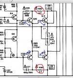
In the drawing above, it shows Q6 Vce being +1.2V to -1.2V. Q6 Vce should be somewhere close to 2.4V starting out. Verify the voltage supply rails on the collectors of Q14(12) and Q10(8). Q6 is to act as a clamp providing a constant bias (basically ) of voltage between the bases of the drivers and output devices. By adjusting the value of R49, Q6 Vce changes. You want to change it so that the voltage between the bases of the output transistors yields the proper voltage (mV) across R71. There should be something around 1.2V across R69.
) of voltage between the bases of the drivers and output devices. By adjusting the value of R49, Q6 Vce changes. You want to change it so that the voltage between the bases of the output transistors yields the proper voltage (mV) across R71. There should be something around 1.2V across R69.Concentrate on Q6 for now. Something is wrong with those readings, with 6 volts across C and E the amp should have gone up in smoke.
Lets see what is going on. With 6 volts across C and E do as CBS240 mentions and measure the voltage across R69 You should read around 4.6 volts DC (at which point the amp should be smoking but I take it its not). So lets see what you actually get.
Lets see what is going on. With 6 volts across C and E do as CBS240 mentions and measure the voltage across R69 You should read around 4.6 volts DC (at which point the amp should be smoking but I take it its not
). So lets see what you actually get.Hi
Time does fly 5 days since I last managed to make time to look at my amplifier project!
Thanks for all the help, this is an awesome forum.
Mooly I measured across R69 and R70 and both read 0V.
I am starting to think that I am doing something wrong. Although I can't see what these seem straight forward measurements.
It's no problem
If you have no voltage across R69 and 70 then the next step is to measure across Q6 and Q7. On the manual its shown as around 2.4 volts (the plus and minus 1.2 volts on the base of both drivers added together).
So measure across Q6 and Q7 and see what you have. That voltage should alter with adjustment of the trimmers. If it doesn't reach around that value (2.4 volts) then that is why you have no voltage across R69/70.
First thing is to see what you actually get.
As you say, its been a few days and I see you did that. Sorry my mistake.
You need to measure (and you must be careful) the base and emitter volt drops of the two driver and two output devices.
You mentioned before 6.6 volts across Q6 I think. That voltage is "getting lost" somewhere. If there really is 6.6 volts across Q6 then there should also be 6.6 volts across the bases' of the two drivers (check it as there could be open print somewhere). If there is 6.6 volts and no voltage across R69 then one or both drivers is faulty or incorrect/incorrectly fitted in some way.
Are the 4.7 ohms OK ?
The voltages between across all the base emitter junctions (the blue lines) can not exceed around 0.7ish volts on a good transistor (that figure is determined by the physics of the silicon devices). If any device has over that then its faulty or incorrect in some way.
And be careful because 6 volts across Q6 should absolutely fry the output stage once you have found the problem. Always start with the trimmer to give a low voltage across Q6 and then turn it up observing.
Attachments
I still get the same, I adjust the trimmer and it gives me 1.75V- 6.6V across Q6ce. Yet R69 still remains at 0V. Does this mean Q8 and Q10 are faulty?
Are the values on the other channel correct? 0.3v to 0.48v across Q7 and 0v - 4mv across R70?
I have previously replace R69 and R71, R69 had burned and left a ugly mark on the board. Not sure if this clue helps.
Are the values on the other channel correct? 0.3v to 0.48v across Q7 and 0v - 4mv across R70?
I have previously replace R69 and R71, R69 had burned and left a ugly mark on the board. Not sure if this clue helps.
Lets concentrate on just one channel to begin with.
Q8 is definitely either faulty, or incorrect in some way (PNP instead of NPN and/or incorrectly fitted) but there may be more than this one problem. You need to check all the transistor types and pin outs.
The 4.7 ohms can be measured in circuit with the amp off.
The fact that the bias voltage swings from 1.7 to 6 volts as the trimmer is adjusted shows that this part of the circuit is fine.
Your problem is definitely around the four transistors, the 330 ohm and the two 0.22 ohms. If those 6 components are OK (and those 4.7 ohms) then it will adjust and work correctly.
You need to check very carefully the type of device you fitted and the polarity and connections.
Before you replace anything and switch on make sure you have the trimmer set to give minimum volts across Q6.
just take it slowly and be methodical.
^this and determination. And rest assured there's plenty of knowledgeable people to help you here.
- Status
- This old topic is closed. If you want to reopen this topic, contact a moderator using the "Report Post" button.
- Home
- Amplifiers
- Solid State
- Newbie vs Pioneer SA408