https://skydrive.live.com/redir?resid=FEB1098345877E73!316&authkey=!NclootF*Jp4$
I have an amp (Or “I Have A Dreame” HA) I built and need to replace, (want to) the Blazer boards, 300-500watt. Given to me, but no info on them and I would rather stick to something with more support. It has the following design features/requirements (will try to attach PICs):
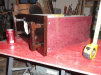
1. Built in a Monoblock Config in a single chassis.
2. Installed Two 600va Torids with EIGHTEEN 10,000uf Panasonic Caps (4 per rail), lots of …Brother was a elec parts buyer, so caps were free and Apexjr had torids on sale.
3. Soft start and speaker delay/protection installed
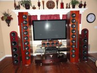
4. Was driving large 3way line arrays dip down to 2ohm a cer freq range, and did an excellent job. So 4-8 ohm needed.
5. MY RAILS ARE +/- 63VOTS.
6. Heat sinks, two 6x9, 9 in vertical fins placement.
My limiting factors are the +/-63volt rails and the heat sinks being two. Two separate heatsinks may or may NOT limit me to two PCB.
Some I have looked at THAT HAVE PCBs
A. The Honey Badger. Looks good, although I’m not sure about the construction. With the long boards and transistor placement. (?)
B. ESP mosfet amp Project 101. Simple design, or too simple? Project 101 - High Power, High Fidelity Lateral MOSFET power amplifier
C. AmpsLab , Auss Amps and others are pricey $$$$$.
I also have an Adcom GFA 555II with +/-80v rails I am going to modify. Driver board has too much discoloration, so I will gut it. The Torids primary can be wired for 215/220VAC. This will give me apx +/-40v rails. The power rating pri/sec ratio will be the same. Correct me if I am wrong, the current rating can not be exceeded. Most insulation is good for up to 600volts.
There are a few E-Bay boards that might fit the bill, just not sure about quality control, if any.
Any help PLEASE
Paul EMC
USN Retired
no pics.....
Your submission could not be processed because a security token was missing
I have an amp (Or “I Have A Dreame” HA) I built and need to replace, (want to) the Blazer boards, 300-500watt. Given to me, but no info on them and I would rather stick to something with more support. It has the following design features/requirements (will try to attach PICs):
1. Built in a Monoblock Config in a single chassis.
2. Installed Two 600va Torids with EIGHTEEN 10,000uf Panasonic Caps (4 per rail), lots of …Brother was a elec parts buyer, so caps were free and Apexjr had torids on sale.
3. Soft start and speaker delay/protection installed
4. Was driving large 3way line arrays dip down to 2ohm a cer freq range, and did an excellent job. So 4-8 ohm needed.
5. MY RAILS ARE +/- 63VOTS.
6. Heat sinks, two 6x9, 9 in vertical fins placement.
My limiting factors are the +/-63volt rails and the heat sinks being two. Two separate heatsinks may or may NOT limit me to two PCB.
Some I have looked at THAT HAVE PCBs
A. The Honey Badger. Looks good, although I’m not sure about the construction. With the long boards and transistor placement. (?)
B. ESP mosfet amp Project 101. Simple design, or too simple? Project 101 - High Power, High Fidelity Lateral MOSFET power amplifier
C. AmpsLab , Auss Amps and others are pricey $$$$$.
I also have an Adcom GFA 555II with +/-80v rails I am going to modify. Driver board has too much discoloration, so I will gut it. The Torids primary can be wired for 215/220VAC. This will give me apx +/-40v rails. The power rating pri/sec ratio will be the same. Correct me if I am wrong, the current rating can not be exceeded. Most insulation is good for up to 600volts.
There are a few E-Bay boards that might fit the bill, just not sure about quality control, if any.
Any help PLEASE
Paul EMC
USN Retired
no pics.....
Your submission could not be processed because a security token was missing
To start with, I believe most "high power" amps these days are over 1000 W continuous, as the PV-1.3K I have been monkeying with the last year. I would say 300-400 w is medium power. the Honey badger looks like an excellent choice in this range. The alternative I would consider first would be the LME49810 driver IC, with suitable output transistors located on your heat sink. The schematic is on the datasheet available from datasheetcatalog.com or from your favorite retailer.
The large heatsinks may inhibit finding a PWB with the built in transistors that match up. I don't think locating the output transistors away from the driver board is a huge problem. This PV-1.3k has the output transistors on a heat sink assembly 12" away by round cable from the driver PWB's.
Soft start is something the PV-1.3k did not have, and it was dimming the lights at turn on, so I installed a GE CL101 variable resistor in series with the primary. Which number GE variable resistor you install would have to do with the load of your transformer/capacitor combination.
Make sure with that much capacitance you don't short out the rectifier bridge with turn on current. Some rectifier bridges are internally fused, others will just short across and burn up your power transformer. So buy the right ones.
Excess capacitance on the rails will also make it harder to break the current with a safety circuit if an output transistor shorts. Relays, FET's all have short circuit current ratings, 63 VDC is a very tough load to break at huge short circuit currents. If you don't have a protection circuit, use only dispose-a-speakers is my opinion. I've blown up one speaker of an unrepairable speaker pair twice, with a transformer coupled tube amp. So any solid state amp attached to my $600 each speakers now will have a DC protection circuit installed. The protection circuit in the PV-1.3k was not adequate, to judge by the lands melted off the PWB to the protection triac, so that is under design at this point. You get much less help here on protection circuit; a lot of people wave their hands and don't actually test this accessory circuit with a simulated failure.
Have fun.
Last edited:
Thanks for the reply!
The soft start and speaker protection have been working for a few years now. The speaker protection saved my *** a few times while tweaking. The LM49810 looks interesting. I will check it out. Can't remember the thermistor rating. It works fine with powerloss and lights are fine.
The soft start and speaker protection have been working for a few years now. The speaker protection saved my *** a few times while tweaking. The LM49810 looks interesting. I will check it out. Can't remember the thermistor rating. It works fine with powerloss and lights are fine.
- Status
- This old topic is closed. If you want to reopen this topic, contact a moderator using the "Report Post" button.