Several diagrams posted here show exactly where the terminals BASE, EMITTER & COLLECTOR always are for every TO3P, TO247 etc. power transistor, NPN or PNP types, just as you saw on the datasheets. Every datasheet specifies the specific transistor's pinouts, whether it is a small signal, medium or power transistor, with few variations. If it's all too hard to find suitable datasheets from Datasheetcatlog, for instance, then Google "2SD778 pinout" or whatever particular transitor type and look at the pics. This is fundamental, how to search for anything on your PC, technique.
However, if you are really asking us for a circuit diagram and how to identify the BASE, EMITTER & COLLECTOR of transistors from that, you really do need to start reading about electronics symbols, how transistors work and how to identify their terminals from any schematic diagram. Those basics have also been posted and explained here already but it doesn't seem to be understood yet. Perhaps it's time to read slowly and digest this information, visit the websites and do further reading, test yourself for your grasp on where the leads are on any transistor you have, check and prove that by measuring their diode voltages on your meter and prove to yourself that you are aren't just lucky by following the pictures but actually do understand what the symbols indicate as the BASE, EMITTER & COLLECTOR and that you are learning how transistors work.
That will make a fine start to real DIY. If you are also finding it hard to understand how several transistors can work together, you won't be alone as not many people really do. The key is building and doing known designs repetetively and testing out what they do. Read and understand the designer's notes and make adjustments to get it just right. Measure what happens with DC and AC and keep your own test notes with the design until you have a grasp of what makes it tick.
I should point out that an oscilloscope is the single best help to seeing what goes on dynamically in a circuit as signals affect its operation. These are expensive instruments, even though relatively cheap 2nd hand. You can though, download free oscilloscope software for your PC and see most of the audio spectrum and what your latest creation does to it at no cost with demo software like Osci. There are many freeware, shareware oscilloscope programs though and most are good fun to mess around and see what goes on when your amp is misbehaving. Have fun.
Is the issue more fundamental?
Do you know when we refer to the various terminals, such as base, collector and emitter, exactly what these are for? I'm not sure I'm clear on wether you are having difficulty identifying these leads on a given device, say by looking at the data sheet, or if you don't know what the terminals do on the devices.
I'm more than happy to provide a little guidance, and I'm sure some others would as well, but we need to get a better idea of what your current level of knowledge is. Many folks here expect a certain minimum level of understanding to already be present in someone when they respond and can get put off when that minimum doesn't seem to be met.
I know you have been provided several links to decent websites that cover some basics, have you read and understood at least some of that? Give us some sense of what level we need to operate at.
i do know how to make a simple single transistor 2 capacitor with 2 resistors amplifier with low wattage from a 5.0 volt power supply that is no problem for me but anything more get's confusing as to not knowing which wire goes to which lead
Do you know when we refer to the various terminals, such as base, collector and emitter, exactly what these are for? I'm not sure I'm clear on wether you are having difficulty identifying these leads on a given device, say by looking at the data sheet, or if you don't know what the terminals do on the devices.
I'm more than happy to provide a little guidance, and I'm sure some others would as well, but we need to get a better idea of what your current level of knowledge is. Many folks here expect a certain minimum level of understanding to already be present in someone when they respond and can get put off when that minimum doesn't seem to be met.
I know you have been provided several links to decent websites that cover some basics, have you read and understood at least some of that? Give us some sense of what level we need to operate at.
For learning without burning anything, I highly recommend also downloading and using the free LT-Spice software. Within minutes, you can draw a schematic of a simple transistor circuit or amplifier. After that, it's like pure magic. You can run the circuit, in the simulator! Your mouse pointer turns into an oscilloscope probe, and much more. It's like having a whole lab full of equipment and a warehouse of components that are never out of stock, except that you can't accidentally blow up anything or start any fires, or electrocute anyone. (You can still check whether or not anything WOULD have burned: Holding down ALT makes the mouse pointer into a "power dissipation" probe, which works on every kind of component.)
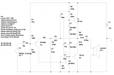
Here's an example of a relatively simple amplifier schematic that in practise should work though I haven't built this particular circuit (see attachment). There are simpler but this shows the typical 'three stage' design.
This is the connection diagram. It shows the power source as a 12V battery and everything it connects to. It shows every connection you need to make to physically build it. There are four transistors and this is in fact a 'Class B' push-pull type of amplifier you have been asking about. I know you have mentioned being of limited means but to step in this direction you will either have to do some scavenging of old electronics or find a way to buy a few components if you seek to make anything like this. For a conventional type of design that will drive an actual speaker this is about as easy as they come.
This was created using LTSpice from Linear Technology available here. The software is absolutely safe and free, many people here, including myself, use it to verify an idea before building a circuit. As Gootee mentioned you can play all day and just see what happens.
Look at it and tell us what you see or recognize in the diagram.
Attachments
- Status
- This old topic is closed. If you want to reopen this topic, contact a moderator using the "Report Post" button.