leach superamp
Agree with here.
Is it possible to experiment shortening some wires?
As stated by Mr. Leach:
"If you build this amplifier, you must keep the wiring between the heat sinks and the circuit boards as short as possible if you don't want oscillation problems."
Agree with here.
On the agenda today is to swap out the front end transistors and put some twists in the wires going to the heatsink. i should have done that the last time when I rewired all of it and mounted it on the heatsink. Shouldn't take much work and it will be one less thing to worry about. Could be just me but this amp seems to be sounding better the longer I play it.
Hi Anthony,
No I haven't added anything to the power caps yet. I may go to 4 caps in the final design. I have four 10,000uf 100V caps that I bought for this amp. I may do a CRC with those instead of using the two caps I'm using now. I can add the resistors then.
I did look up the G Randy Slone books but have not ordered them yet. Trying to find them in digital so I can have it on my E-reader. I will get them.
Base stopper resistors and base-collector snubbers could be necessary; I'm having some interesting issues with ThermalTrak transistors and will be doing this as a check that there might be some oscillation I'm not catching even with a 100 Mhz 'scope.
I didn't want to put base stoppers on the output transistors as that'll reduce the effectiveness of charge suckout by the driver transistors but I need to do this as a reality check for very low-level crud I'm seeing on the 'scope that's higher than I would like to see.
I didn't want to put base stoppers on the output transistors as that'll reduce the effectiveness of charge suckout by the driver transistors but I need to do this as a reality check for very low-level crud I'm seeing on the 'scope that's higher than I would like to see.
Last edited:
I didn't get a chance to swap out the transistors, I took some time to reset the bias and played it some more, I have to say this amp is growing on me. While I was working on the bias, I played some of my other amps. After listening to the Superamp for the last couple of days, the Low TIM was lacking. I think I'm going to like the Superamp.
I hooked up the sinewave and scope. I discovered that the generator would put out more voltage on a square wave so I used that. I still couldn't get the amp to distort, even at 86VAC output.
Right channel, generator on bottom, output on top
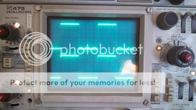
right channel, generator on left, output on right.
Left channel, generator on bottom, output on top.
left channel, generator on left, output on right.
I hooked up the sinewave and scope. I discovered that the generator would put out more voltage on a square wave so I used that. I still couldn't get the amp to distort, even at 86VAC output.
Right channel, generator on bottom, output on top

right channel, generator on left, output on right.

Left channel, generator on bottom, output on top.

left channel, generator on left, output on right.

Hi Anthony,
I can only tell you what I saw. You can see in the pictures what I saw. There is no load on it. I can't say what ohm the amp is running at. I'm very new to using a sine wave generator and scope. That is why I took the pictures, so you guys who know could tell me.
i think I figured out why it was feding back the other day. When I hooked up the input, I only connected the ground to one channel. The other lead was connected to the inout on both. Once I connected the ground to both, the feedback went away. I haven't seen it again. I have set it all aside now until I can get some aluminum plate to build the chassis. I may set it up tomorrow and take voltage measurements so I can update a schematic for future use and for the benefit of others who may be down this same road.
Blessigs, Terry
Hi Terry, a quick number crunch would say what the o/p is doing.. ac output v divided by R load = current then times by ac volt out = power before clip. say your amp was doing 20 o/p so 20 over 8 ohms is..2.5 amp times by 20v is 50w... it's just a refresher note as we all from time to time for get stuff.. Also measure the ac volts at the i/p of the amp and o/p before clipping kicks in.
regards Anthony.
regards Anthony.
Is your scope set to 20v max volt/div..
I don't know. I have all the switches all the way to the top.
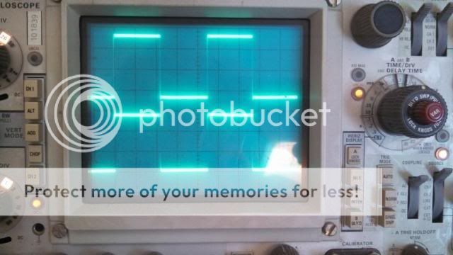
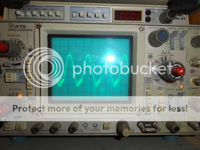
This picture is basically how it was set except it was set to chop and of course the Volts/Div and Time/div were maybe a little different. I was using it to work on a pre-amp today so those got moved.

Your scope settings...
CH1 is set at 1V/div
CH2 is also set at 1V/div but it is now in uncalibrated mode. Turn the red knob clockwise to the click end and the UNCAL indicator on its right should go off.
Same is the case with sweep setting. The knob on the right that sets the time/div has a red knob. Turn it clockwise to the click position and the UNCAL indicator on its left will go off.
Gajanan Phadte
Last edited:
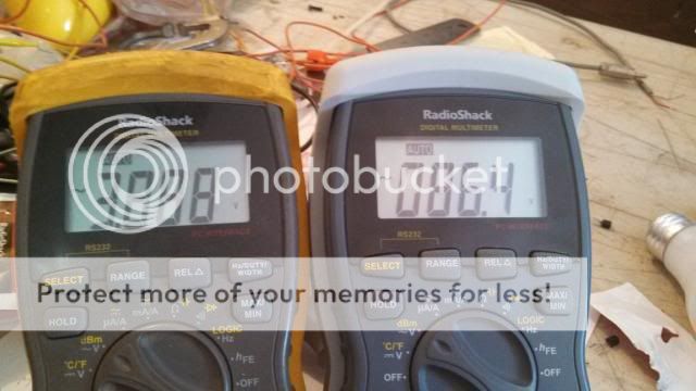
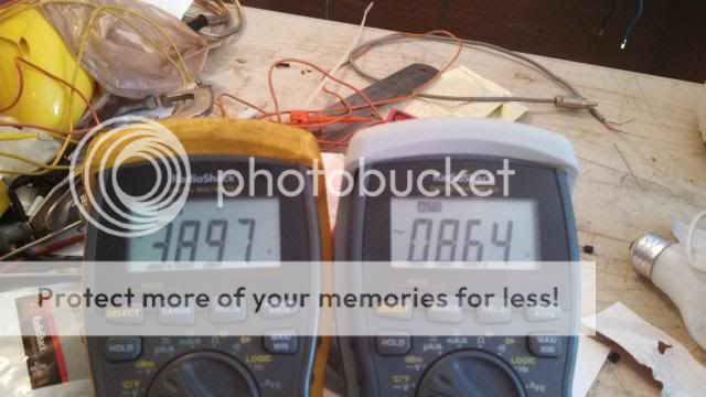
Hi Terry, looking at post number 167 your meter's appear to be giving different readings with one under 4 ac volts and the other 86v... If the amplifier was giving such high o/p your jbl's would be cooked at that power. your need a heavy duty test load to check power out put of amplifier.
regards A.
regards A.
Hi Terry, looking at post number 167 your meter's appear to be giving different readings with one under 4 ac volts and the other 86v... If the amplifier was giving such high o/p your jbl's would be cooked at that power. your need a heavy duty test load to check power out put of amplifier.
regards A.
Mabe I wasn't clear. I didn't have anything hooked up to the output except for the scope and DVM. The meter on the left is hooked up to the input with the sine generator and the meter on the right is hooked up to the speaker jack. I do have a dummy load coming should be here any day. Once I have it I will run the test again
Your scope settings...
CH1 is set at 1V/div
CH2 is also set at 1V/div but it is now in uncalibrated mode. Turn the red knob clockwise to the click end and the UNCAL indicator on its right should go off.
Same is the case with sweep setting. The knob on the right that sets the time/div has a red knob. Turn it clockwise to the click position and the UNCAL indicator on its left will go off.
Gajanan Phadte
Hi Gajanan,
Thanks for the info. I have had no instruction in using a scope aside from what I have picked up here from little things like this. I should probably look up some tutorials or something. I was using the little red nobs to adjust the height of the wave to try and fit both waves on the screen. I didn't know they should be locked. This is probably a better picture of how it was set when I was testing the leach but I'm not sure it is clear enough to see any of the settings.

Thanks again
The ghost is back. It is a very puzzling thing. I had the amp playing all morning without a hitch. When the mail came my 300w, 8R resistor was in it so I was pretty excited about hooking it up to do some tests. Well I checked the right channel with the resistor hooked up to the outlet and I used a preamp so I could get a higher voltage on the input. I was able to get 59VAC on the output before it clipped. That was with 2.7VAC on the input. I then went about hooking up the left channel but when I powered it up it blew the fuse on the +rail. I figured I might have shorted the output while hooking everything up so I replaced the fuse and fired it up again. I checked all the voltages and everything looked good so I hooked up the input and began running up the sine wave. When I get to about 20Vac on the output is see the clipping start again. I can't believe my eyes. To test, I disconnect the dummy load and the clipping goes away. I reconnect and it's back. So recheck all the voltages and all looks right. If I run it up without a load everything looks fine. Another weird thing was I connected the speaker once and It went all the way to 59VAC on the output without clipping. So I rehook the dummy load and it clips again. However when I tried hooking up the speaker again it clipped this time. The other thing is that the heatsink got really hot. I though maybe the bias has changed so I rechecked that but it was good.
Any ideas? Any suggestions why it is only clipping on the bottom side of the sinewave?
Thanks, Terry
Any ideas? Any suggestions why it is only clipping on the bottom side of the sinewave?

Thanks, Terry


- Status
- This old topic is closed. If you want to reopen this topic, contact a moderator using the "Report Post" button.
- Home
- Amplifiers
- Solid State
- Leach Superamp, round 2