I like things a bit easier to follow so I just print a few oversize schematics out and pencil voltage readings directly onto a copy and use a pen to mark what is specified, then give the sheet a date or other reference so I know where I am or was yesterday etc. If you want to post it, you can still scan the image and likely get more help because the info. is in one easy look....... I was typing up a new chart. Now I have to start over becaaus a few of the voltages changed......Fun Stuff!
")
Yeah, I can put it on a schematic I have been writing them on the parts layout and then using the schematic to check it. Unfortunately, there is nothing specified. If I had a working unit, I could at least compare voltages but I am just shooting in the dark right now. I know I still have something wrong because I am getting 1.6V over the 100ohm resistors I have in place of the fuses and according to Leach, I should be seeing less than 1/2 a volt. Plus the fact that both boards are not reading the same.
I'll do a Schematic with voltages and post it. maybe that will help someone help me.
I'll do a Schematic with voltages and post it. maybe that will help someone help me.
It's just a generalisation but 'divide and conquer' is the strategy for isolating problems.
R32 and 33 control current to the front end and if you see most of the 1.6 volts drop (or rather 16 mA) also flowing through these, you know where to focus your attention. Actually, in an amp this big, 16 mA is not far off correct and I would suspect that "half volt drop" figure, which implies only a tiny 5mV current to the input and VAS stages - even if they hogged all that current.
I realise some of the amplifier has actually been disabled by removing parts but I assume the front end is intact so that feedback is working and DC readings are sensible, otherwise the test regimen is a waste of time.
Dr Leach suggested to test the boards prior to attaching the outputs. Probably not a bad idea since I obviously have something wrong because my two boards don't agree. I just wish he had given some voltage specs so I had something too go by. I don't understand electronic circuitry well enough to know where the different voltages originate. I'm hoping someone who does will be able to look at what I have and give some suggestions as to where to look. I will post some schematics tomorrow with my results. Hopefully my scope probes will arrive soon so I can post some results from that as well.
Blessings
Blessings
I'm surprised there isn't a schematic available with typical voltages marked on it.
I can't offer any specific help, but with one amp that gave me trouble, when I returned to it with fresh eyes (and more learning), I discovered that I'd made inappropriate substitutions, and put a couple of transistors in wrong.
I have encountered a number of PC boards which had shorts between traces or cracks in traces that were so small I needed a magnifier to see them, and, quite a few plated-through holes that weren't. There's been the occasional component which had leads which solder just didn't stick to. An adjustable desk lamp and magnifying glasses are helpful; backlighting a board helps with spotting cracked or shorted traces.
Dr Leach suggested to test the boards prior to attaching the outputs. Probably not a bad idea since I obviously have something wrong because my two boards don't agree. I just wish he had given some voltage specs so I had something too go by. I don't understand electronic circuitry well enough to know where the different voltages originate. I'm hoping someone who does will be able to look at what I have and give some suggestions as to where to look. I will post some schematics tomorrow with my results. Hopefully my scope probes will arrive soon so I can post some results from that as well.
Blessings
yes, but it doesn't mean his method is the only way there is to set up his amps...
if you understand how his circuit works, then you will know more or less what the voltages are supposed to be at various nodes in the diagram....then knowing that you can check accordingly...
i know of one builder building the 5 pairs lo-tim who was able to make it work from first power up....i hope he chimes in...
this amp can work from first turn on only and only if there were no mistakes in wiring up and board stuffing....
so check and double check for mistakes, be deliberate and do not be in a hurry, it will be better if someone with fresh eyes can sit with and look at your work....
I'm surprised there isn't a schematic available with typical voltages marked on it.
i remember someone posted that drawing here some years back...
Yeah, these are home brew boards. It is possible that I have missed something but I just went over the whole board and checked for continuity. Look good but I could have missed something.
I have already found some things I missed before I put it way a few years ago. Back then I was anxious to get onto the next project. This is my project right now so I am determined to get it working. Please stick around. You may see something no one else does.
I have already found some things I missed before I put it way a few years ago. Back then I was anxious to get onto the next project. This is my project right now so I am determined to get it working. Please stick around. You may see something no one else does.
Start fresh, keep all your earlier papers aside. Take the parts list and check all the resistors for their value using a DMM. Tick mark it on the list.
When I am assembling a board, I gather all the required parts and then assemble. This is needed for the resistors especially, as you will not miss the values and any mistake will show up when you find that the remaining resistors are of incorrect value. You can then find out your error and correct it.
Never have all your resistors' assortment at hand and assemble. Mistakes will be difficult to locate.
Gajanan Phadte
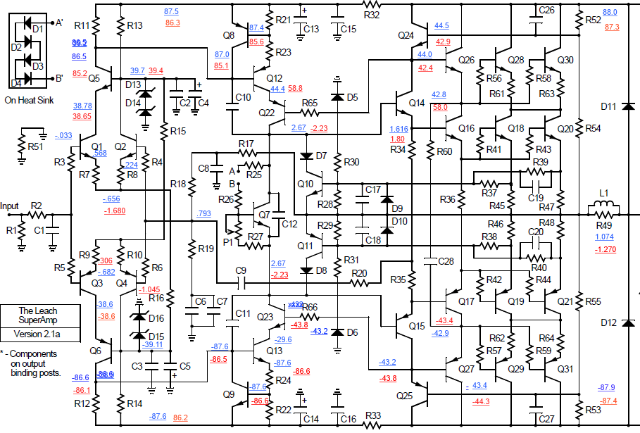
OK, I sat down this morning and took new measurements, one board at a time. I have tried posting them on a schematic I'm not sure how well it will all show up on here but here goes.
I was surprised to find that most of the numbers were very close, especially given that the rails changed slightly. However, everything looks good side to side except for the collectors for Q12 and Q16 on the red board. They are both over 58V. Any idea where this is coming from? I replaced Q12 and Q22 and still no change. Haven't touched Q16 since the other change made no difference.
Also I have about 1.5V drop across the 100ohm 1/4W resistors in place of the fuses. Leach says it should be less than .5V
Thanks, Terry
Attachments
Do you have an oscilloscope and signal generator? If things aren't smoking, I trace out waveforms to see how far the signal is getting and observe if oscillation is present.
Haven't attempted to build a Superamp, but I'm hoping you'll get your's running and we can study the results. Documenting the proper working voltages would be very useful. I'm intrigued by the cascoded VAS stage.
If you get really stuck, I could try testing one of your boards here with a single output quad.
I do have a scope and a signal generator. Unfortunately, I misplaced the probes. I have a couple coming. Should be here this week. I will probably need help since it's been so long since I did it.
I will happily mark up a schematic with voltages once I get it working. I agree, it would be very useful to folks wanting to build one of these.
Blessings, Terry
I will happily mark up a schematic with voltages once I get it working. I agree, it would be very useful to folks wanting to build one of these.
Blessings, Terry
your Q26 base emitter is reverse biased, that is the problem...so with your Q22, Q23......
voltage between base and emitters of small trannies must be around 0.6v...
or that you inserted them correctly into the board..
first make sure that you got the right trannie inserted in those spots..
voltage between base and emitters of small trannies must be around 0.6v...
or that you inserted them correctly into the board..
first make sure that you got the right trannie inserted in those spots..
your Q26 base emitter is reverse biased, that is the problem...so with your Q22, Q23......
voltage between base and emitters of small trannies must be around 0.6v...
or that you inserted them correctly into the board..
first make sure that you got the right trannie inserted in those spots..
Rats, I was hoping you onto something but no such luck, the parts are right and in the right orientation.
As I said, I don't really understand how the voltages are produced other than know that a resistor will reduce it. I see 58V and I have no idea how that got there. If there are any other readings you need to help get to bottom of this I will be happy to check for them. I have spent a bit of time checking both boards to look for anything different but I can't see anything.
Thanks, Terry
Disable or isolate VI limiter...It seems it affects the circuit operation..
An externally hosted image should be here but it was not working when we last tested it.
I agree. Now if someone can tell me what is causing the voltage offset I will be a happy camper.
if you can solve the wrong voltage readings, i believe the output offset will solve itself...so first things first....that output offset is far from my mind looking at your readings...
Disable or isolate VI limiter...It seems it affects the circuit operation..
An externally hosted image should be here but it was not working when we last tested it.
Are you saying to disconnect where the red X's are?
Edit; After looking at the board, R37-R40 aren't attached. They go to the outlets for the power devices which are on another board which is not connected. I can disconnect the 4 diodes. I will do that and take another reading.
if you can solve the wrong voltage readings, i believe the output offset will solve itself...so first things first....that output offset is far from my mind looking at your readings...
I didn't mean the offset at the output. I was talking about the -43V on the one side and the 58V on the other. Ricdelros may be onto somethng. I remember that either D7 or D8 was fluctuating so much I couldn't get a reading.
Thanks Guys!
Last edited:
- Status
- This old topic is closed. If you want to reopen this topic, contact a moderator using the "Report Post" button.
- Home
- Amplifiers
- Solid State
- Leach Superamp, round 2