Hi Guys,
Back in 2005 I attempted to build a Superamp as my second project. I actually started it while I was building my first amp which was a Elliot P101. The reason I started the Superamp was because I bought the wrong transformer for the P101 and the Leach was a good fit for the transformer.")
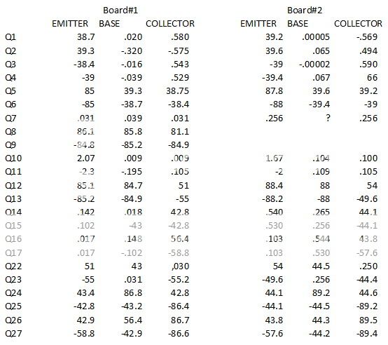
Anyway, I had trouble getting the Leach to work so I put it aside and went on to other amps figuring that someday I would gain enough experience to be able to tackle the Superamp again. As I continued I built KSA50 with TO3 outputs, a Leach Low TIM, another KSA50 with plastic outputs, an Aleph-X and a Symasym. At that time my 12 year old son dragged me kicking and screaming into RC airplanes and I put DIY audio on the back burner. Well my son has grown up and moved on to other things and I have recently retired so I have a lot more time on my hands. A couple of weeks ago I sat down and got out my KSA50 that had quit working and fixed it. That was so much fun that I also got out the ALeph-X that was having problems and fixed that as well so now I am going to try to tackle the Superamp once again. I have removed the output leads from the board so I could test it and see if I can get it working. I am attaching the voltages I got from the test. I'm hopeful that one of you guys who are familiar with this amp will be able to look at them and see if you see any glaring problems. I do have a scope but haven't been able to find the proper leads so I ordered some and should get them shortly. Hopefully one of you can walk me through hooking it up.
So here are some picks.
Thanks, Terry


Back in 2005 I attempted to build a Superamp as my second project. I actually started it while I was building my first amp which was a Elliot P101. The reason I started the Superamp was because I bought the wrong transformer for the P101 and the Leach was a good fit for the transformer.
Anyway, I had trouble getting the Leach to work so I put it aside and went on to other amps figuring that someday I would gain enough experience to be able to tackle the Superamp again. As I continued I built KSA50 with TO3 outputs, a Leach Low TIM, another KSA50 with plastic outputs, an Aleph-X and a Symasym. At that time my 12 year old son dragged me kicking and screaming into RC airplanes and I put DIY audio on the back burner. Well my son has grown up and moved on to other things and I have recently retired so I have a lot more time on my hands. A couple of weeks ago I sat down and got out my KSA50 that had quit working and fixed it. That was so much fun that I also got out the ALeph-X that was having problems and fixed that as well so now I am going to try to tackle the Superamp once again. I have removed the output leads from the board so I could test it and see if I can get it working. I am attaching the voltages I got from the test. I'm hopeful that one of you guys who are familiar with this amp will be able to look at them and see if you see any glaring problems. I do have a scope but haven't been able to find the proper leads so I ordered some and should get them shortly. Hopefully one of you can walk me through hooking it up.
So here are some picks.
Thanks, Terry


Last edited:
Hi, looking at your reading there's odd different volt reading...did you match all the resistors and transistors? pcb 2 has most off voltages..I would tend to rework that board and bring the voltage up slowing plus test the volts at the o/p end anything over 100mv would be to high.
the old lamp tester will show if the amp is ok via quickly going bright at power up then off or use a lower supply to check the amp..
the old lamp tester will show if the amp is ok via quickly going bright at power up then off or use a lower supply to check the amp..
Hi Amptech.
Thanks for taking time to help me.
I should have mentioned that the mains voltage changed throughout the day. I also used a variac so the rails were a little different from board #1 to board #2. Even with that, I noticed that the main voltage changed a little while I was in the middle of testing one of the boards. I may have confused the ECB's on some of the transistors as I had to take the reading from the bottom of the board and it wasn't always easy to see which pin was which. I am mainly interested in whether there are any numbers that are off enough to indicate any devices that are not in the ballpark. I have read the Leach document many times. Like I said, I don't have my scope available yet so I can't take any other reading at this time.
I do remember taking time to match things as well as I could when I was building this amp.
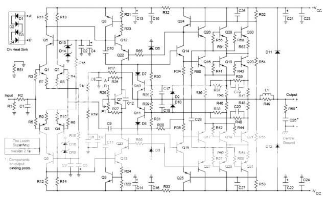
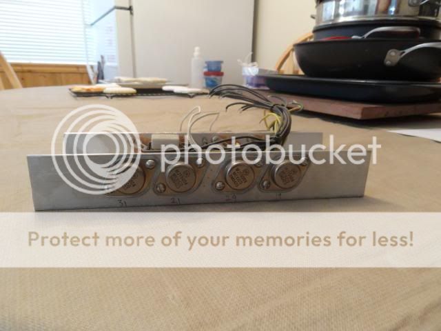
Per the Leach docs, I have 100ohm resistors between the output and the emitters of Q16 and Q17. I believe I got 17mv on one board and 102mv on the other. Q7 is shorted per the docs so the bias pot is out of the circuit. Keep in mind that don't have the power transistor connected at this time.
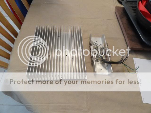
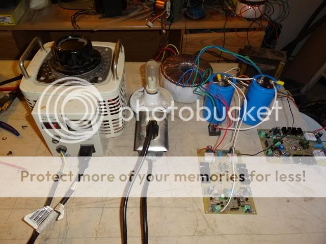
Along with using a variac, there is a 100 watt light bulb between the variac and the transformer. There are also 100ohm 1/4W resistors between the power supply and the boards. Believe me, I took it very easy bring these boards up to voltage. I was very pleased that nothing got warm on the board.
Here is a pic of the setup I used to test.
Thanks for taking time to help me.
I should have mentioned that the mains voltage changed throughout the day. I also used a variac so the rails were a little different from board #1 to board #2. Even with that, I noticed that the main voltage changed a little while I was in the middle of testing one of the boards. I may have confused the ECB's on some of the transistors as I had to take the reading from the bottom of the board and it wasn't always easy to see which pin was which. I am mainly interested in whether there are any numbers that are off enough to indicate any devices that are not in the ballpark. I have read the Leach document many times. Like I said, I don't have my scope available yet so I can't take any other reading at this time.
I do remember taking time to match things as well as I could when I was building this amp.
Per the Leach docs, I have 100ohm resistors between the output and the emitters of Q16 and Q17. I believe I got 17mv on one board and 102mv on the other. Q7 is shorted per the docs so the bias pot is out of the circuit. Keep in mind that don't have the power transistor connected at this time.
Along with using a variac, there is a 100 watt light bulb between the variac and the transformer. There are also 100ohm 1/4W resistors between the power supply and the boards. Believe me, I took it very easy bring these boards up to voltage. I was very pleased that nothing got warm on the board.
Here is a pic of the setup I used to test.

Last edited:
Hi,
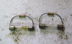
what i do in my super amp builds is to install 10ohm 1/2 watt resistors in lieu of the fuses, having built up the completed amp...
the reasoning here is so that in case there is something wrong, such as reversed connected bias diodes, these resistors will vaporize instead of the output trannies frying out...
i do this one channel at a time...
if the resistors smoke out, then look for wiring mistakes...
correct any mistake and start again...
now if no smoke is coming out, you can the measure the output offset voltage,
it should not be more than +- 100mV...
next comes the idle current adjustment..
you can connect a dmm to read low volts accross the 10 ohm resistors and measure current thru them...
the output trannies are stacked so that they share the rails equally and you can check that that is the case...
Attachments
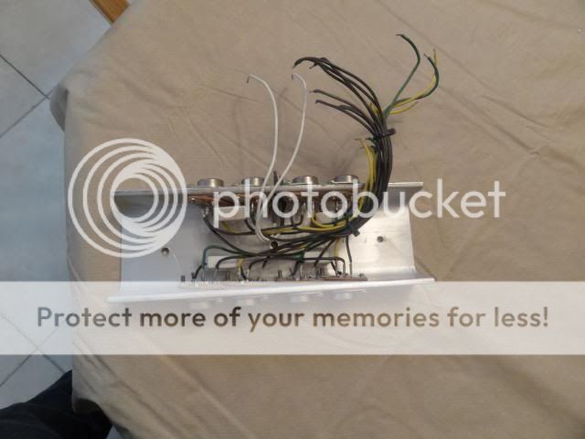
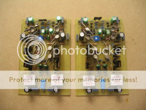
Those two white wires... look like they are connected to the diodes. Please use separate colors for identifying anode and cathode and have to be connected correctly.
Also use three colors for each connection of a power transistor and bunch the wires separately for each transistor.
Edit: The idle current should be adjusted measuring the voltage across R45(R48). Measure across any one resistor and set the current to nearly half of the total specified in each. Both will never be the same.
Gajanan Phadte
Last edited:
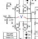
Hope you have connected the diodes D1 to D4.
What is the voltage at the points shown in the jpeg.
Gajanan Phadte
D1-D4 are not yet in the circuit. I am only testing the main board at present. Q7 is shorted.
The voltage between the two point you asked about is .817VDC
AJT
Yes, that is the same way I will do it after I attach the power transistors and D1-D4. That is basically the same proceedure I used for setting the bias on my Low TIM,
Those two white wires... look like they are connected to the diodes. Please use separate colors for identifying anode and cathode and have to be connected correctly.
Also use three colors for each connection of a power transistor and bunch the wires separately for each transistor.
Edit: The idle current should be adjusted measuring the voltage across R45(R48). Measure across any one resistor and set the current to nearly half of the total specified in each. Both will never be the same.
Gajanan Phadte
The wires for the diodes have color coding at the end where they connect to the board. In hind sight I should have used different colors. The wires coming from the power transistors that attach to the board are different colors. They were originally all loose until they were soldered t the main board and then I zip tied them all together. They are that way now because when I took the amp apart after I couldn't get it running, I just left them attached. I will be loosing them when it is time to reattach them to the main board. Do you think it is bad to have them gathered together once the amp is running properly?
Please explain your method for setting the bias. Sounds interesting.
Blessings, Terry
I had adjusted the idle current for my Leach amp by the method as in post #6, but when I measured across the emitter resistors, there was no(very little) current flowing.
Gajanan Phadte
i set the bias to read about 2 volts across the 10 ohm...
if you measure across the emitter resistors,
readings will show lower current, that is to be expected...
AJT
Yes, that is the same way I will do it after I attach the power transistors and D1-D4. That is basically the same procedure I used for setting the bias on my Low TIM,
i build my amp completely, connecting everything up and then i test....i have been building these amps since the 80's...
Do you think it is bad to have them gathered together once the amp is running properly?
Please explain your method for setting the bias. Sounds interesting.
Blessings, Terry
you can tie them up together to tidy up your amp once your amp is up and running....
the 10 ohm resistors that i use is for protection...they are to be replaced with regular fuses once amplifier set-up and adjustment is successful
to know that your amp is working as it should, the output offset voltage needs to be less than +-100mV...
then you should be able to adjust bias with the turn of the 5k trimpot, otherwise even if offset voltage is 0 volts, if bias can not be adjusted at all, then there is still something wrong with your amp...
from the site
Quote
Testing the Circuit Boards
After you solder the parts to the circuit board, it is tested using the same procedure specified for the Low TIM circuit board. First, you must solder the short circuit jumper across Q7 and you must solder the 100 ohm 1/4 W resistors from the loudspeaker output to the emitters of Q16 and Q17. If you don't have a bench power supply that puts out plus and minus 85 to 93 V dc, you can test the circuit board at a lower voltage. I would prefer test voltages of at least plus and minus 50 V dc. An option is to connect bench power supplies in series to obtain the plus and minus 85 to 93 V dc. I have routinely connected two 40 V Hewlett Packard power supplies in series with the positive and negative outputs of a Hewlett Packard 50 V dual power supply, and I have never had any problems. To protect the circuit boards, you might want to put a 100 ohm 1/4 W resistor in series with the plus and minus power supply leads for the tests. The current drawn by the circuit should be low enough so that the voltage drop across these resistors is less than 1 V if nothing is wrong on the circuit board. There are 2 ground wires from the circuit board. Both must be connected when testing the boards.
I can't stress how important it is to be careful in testing a circuit board. Even simple errors can cause the loss of many expensive transistors. I always use current limited bench power supplies to test a circuit board before and after connecting the power transistors. I also bias an amplifier using current limited power supplies in place of the amplifier power supply. When I initially power up an amplifier with its own power supply, I always use a Variac variable transformer to slowly increase the ac input voltage from 0 to 120 V rms while observing the amplifier output on an oscilloscope with a sine wave input signal. If I see anything wrong on the oscilloscope, I turn the Variac to zero and try to diagnose the problem using the bench power supply. I never use a load on the amplifier for these tests.
Unquote
That is the procedure for testing the circuit boards so that your assembly is not drawing heavy current. This prevents damage to the power transistors and is not to be followed beyond, for any further adjustments.
After you found that your boards pass the above testing, assemble all as required to its full requirement. Also connect the RC across the output, but do not connect the speakers.
Quote
It is not necessary to divide the diodes between the two heat sinks because both heat sinks will operate at the same temperature. I recommend setting the voltage across Q7, i.e. the voltage between the collectors of Q22 and Q23, so that that amplifier is biased at 120 mA. This will give the same quiescent power dissipation per heat sink as in the Low TIM Amplifier.
Unquote
The amp is to be adjusted for idle current of 120 mA.
That means 60mA approx. has to pass through each resistor (R45 to R48) on ver2.1a
Using ohms law which is V=IR, calculate the voltage across R45 wherein I=60mA.
When it is mentioned 'voltage across', it means you have to put both the probes on the component mentioned.
This is done by adjusting P1 on a fully assembled amp.
Before going into the adjustment of the amp, the P1 preset has to be set to the position as mentioned on the site.
It is better you refer to the lowTIM (Leach)explanations as they are more beginner friendly.
Gajanan Phadte
Quote
Testing the Circuit Boards
After you solder the parts to the circuit board, it is tested using the same procedure specified for the Low TIM circuit board. First, you must solder the short circuit jumper across Q7 and you must solder the 100 ohm 1/4 W resistors from the loudspeaker output to the emitters of Q16 and Q17. If you don't have a bench power supply that puts out plus and minus 85 to 93 V dc, you can test the circuit board at a lower voltage. I would prefer test voltages of at least plus and minus 50 V dc. An option is to connect bench power supplies in series to obtain the plus and minus 85 to 93 V dc. I have routinely connected two 40 V Hewlett Packard power supplies in series with the positive and negative outputs of a Hewlett Packard 50 V dual power supply, and I have never had any problems. To protect the circuit boards, you might want to put a 100 ohm 1/4 W resistor in series with the plus and minus power supply leads for the tests. The current drawn by the circuit should be low enough so that the voltage drop across these resistors is less than 1 V if nothing is wrong on the circuit board. There are 2 ground wires from the circuit board. Both must be connected when testing the boards.
I can't stress how important it is to be careful in testing a circuit board. Even simple errors can cause the loss of many expensive transistors. I always use current limited bench power supplies to test a circuit board before and after connecting the power transistors. I also bias an amplifier using current limited power supplies in place of the amplifier power supply. When I initially power up an amplifier with its own power supply, I always use a Variac variable transformer to slowly increase the ac input voltage from 0 to 120 V rms while observing the amplifier output on an oscilloscope with a sine wave input signal. If I see anything wrong on the oscilloscope, I turn the Variac to zero and try to diagnose the problem using the bench power supply. I never use a load on the amplifier for these tests.
Unquote
That is the procedure for testing the circuit boards so that your assembly is not drawing heavy current. This prevents damage to the power transistors and is not to be followed beyond, for any further adjustments.
After you found that your boards pass the above testing, assemble all as required to its full requirement. Also connect the RC across the output, but do not connect the speakers.
Quote
It is not necessary to divide the diodes between the two heat sinks because both heat sinks will operate at the same temperature. I recommend setting the voltage across Q7, i.e. the voltage between the collectors of Q22 and Q23, so that that amplifier is biased at 120 mA. This will give the same quiescent power dissipation per heat sink as in the Low TIM Amplifier.
Unquote
The amp is to be adjusted for idle current of 120 mA.
That means 60mA approx. has to pass through each resistor (R45 to R48) on ver2.1a
Using ohms law which is V=IR, calculate the voltage across R45 wherein I=60mA.
When it is mentioned 'voltage across', it means you have to put both the probes on the component mentioned.
This is done by adjusting P1 on a fully assembled amp.
Before going into the adjustment of the amp, the P1 preset has to be set to the position as mentioned on the site.
It is better you refer to the lowTIM (Leach)explanations as they are more beginner friendly.
Gajanan Phadte
Your readings at the beginning are of no use as they are not for a fully assembled amp. By looking at the voltages of Q7, I thought that there was something wrong there.
Even after removing the shorting(at Q7), please keep the series resistors in circuit for the first powering.
Gajanan Phadte
Even after removing the shorting(at Q7), please keep the series resistors in circuit for the first powering.
Gajanan Phadte
Before going into the adjustment of the amp, the P1 preset has to be set to the position as mentioned on the site
this pot is set to maximum resistance, 5k, reason being at this position Vbe's collector voltage is lowest and therefore the idle current of the output stage is also at its lowest...
Thanks to all of you who are participating. You are exactly who I was hoping would show up. I am remembering a lot of this as I get back into it. I remember going through all of this back then.
That is exactly how I did this amp the first time I built it. Unfortunately, when I brought it up to power, I didn't get any signal on the outputs. IIRC, I also burned a couple of resistors. I believe I got the resistor problem sorted out back then but never got it to work. That is why I decided to follow DR Leach's advice and test the board first this time and try to get the boards working first.
This morning I decided to hook both boards up side by side so they would have the same rails and the voltages would more meaningful. I got about half way into checking things when I noticed that on one of the boards, the voltage on Q12C/Q22E was jumping rapidly between 42V-58V. I had some extra devices so I swapped them out with a matched pair. When I checked again, it is still doing the same thing. I can't find anything else fluctuating. The other thing of note is that the Collectors of Q22/Q23 on this board are only about .8V and on the other board they are 2.0V. Perhaps this has something to do with it.
I am going to complete taking readings so I can have a more comprehensive chart.
Thanks again!
i build my amp completely, connecting everything up and then i test....i have been building these amps since the 80's...
That is exactly how I did this amp the first time I built it. Unfortunately, when I brought it up to power, I didn't get any signal on the outputs. IIRC, I also burned a couple of resistors. I believe I got the resistor problem sorted out back then but never got it to work. That is why I decided to follow DR Leach's advice and test the board first this time and try to get the boards working first.
This morning I decided to hook both boards up side by side so they would have the same rails and the voltages would more meaningful. I got about half way into checking things when I noticed that on one of the boards, the voltage on Q12C/Q22E was jumping rapidly between 42V-58V. I had some extra devices so I swapped them out with a matched pair. When I checked again, it is still doing the same thing. I can't find anything else fluctuating. The other thing of note is that the Collectors of Q22/Q23 on this board are only about .8V and on the other board they are 2.0V. Perhaps this has something to do with it.
I am going to complete taking readings so I can have a more comprehensive chart.
Thanks again!
PCB picture is not very clear, but maybe there is partial short-circuiting between voltage amp to-92 transistor and pre-driver black anodized (scratched) transistor heat-sinks ?
I did check for that. There is no continuity between the devices and the heatsinks nor are the heatsinks touching any circuits on the board.
Here are a couple of more recent pics of the boards.


this pot is set to maximum resistance, 5k, reason being at this position Vbe's collector voltage is lowest and therefore the idle current of the output stage is also at its lowest...
So that I'm clear; My pot goes from 0000.2 to 2.2K. 0000.2 is maximum resistance?
while i was in Russia, i walked two guys, one in Manila and another in Hongkong, we did manage to make their amps work.....the guy in Hongkong is now selling SuperLeach amp kits on Ebay....
we did it thru emails.....
Please don't think I am questioning your experience. I am having to refresh my memory at every step. It has been 8 years since I fooled with any of this stuff and I was a novice then.
I did get my Low TIM working so at least I knew then how to bias it. Please believe me, I appreciate your help and hopefully other will learn from this experience.
Blessings, Terry
Last edited:
So that I'm clear; My pot goes from 0000.2 to 2.2K. 0000.2 is maximum resistance?
Blessings, Terry
2.2k is your maximum
Thanks.
I found a couple of mistakes today. R21 and R22 call for 30 ohm and I had 30K in there. I didn't have any 30ohm so I stuck 33ohm in it to see if it would help. Well it stopped the fluctuation but now I have some voltages that are pretty far off between the two boards. I wish I knew what the voltages were supposed to be, at least on a few of the devices. At least I would have something to shoot for. I was typing up a new chart. Now I have to start over becaaus a few of the voltages changed.
Fun Stuff!
- Status
- This old topic is closed. If you want to reopen this topic, contact a moderator using the "Report Post" button.
- Home
- Amplifiers
- Solid State
- Leach Superamp, round 2