I think that using fast output transistors with retro topology, like this one, is asking for trouble with regard to oscillations. Even 70 MHz drivers are overkill. I suggest trying slower drivers and outputs. MJL4281 is overkill for this 25W amp. It's enough to use TIP35C. With them you won't need 10R base stoppers.
you could be right Ivan,
even for JLH amp, it is recommended to use slow devices, like MJL21193/94.
even maouna reported not so satisfactory results with 2sc, but played nice with MJL21194.
I have both , so will use 21194
")
regards
Prasi
From my Slewmaster's days i remember that problem is using slow devices when fast are recommended.you could be right Ivan,
even for JLH amp, it is recommended to use slow devices, like MJL21193/94.
even maouna reported not so satisfactory results with 2sc, but played nice with MJL21194.
I have both , so will use 21194
regards
Prasi
Some 21193-4 smoked under test.
Last edited:
Changing R15 to 25R.
Trimer 220R in R8 position setting for 20mV on 0.47R
The trimmer value in this case is about 75R
That is 42mA bias.
Power supply 50v.
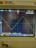
Clear voltage (dummy load 6R)before negative side clip is 13v only when input voltage is 350mV.
The mind point voltage is 23v.
Now it's time to ask.
Is this according to spects?
Trimer 220R in R8 position setting for 20mV on 0.47R
The trimmer value in this case is about 75R
That is 42mA bias.
Power supply 50v.
Clear voltage (dummy load 6R)before negative side clip is 13v only when input voltage is 350mV.
The mind point voltage is 23v.
Now it's time to ask.
Is this according to spects?
Last edited:
Changing R15 to 25R.
Trimer 220R in R8 position setting for 20mV on 0.47R
That is 42mA bias.
Power supply 50v.
Clear voltage (dummy load 6R)before negative side clip is 13v only when input voltage is 350mV.
The mind point voltage is 23v.
Now it's time to ask.
Is this according to spects?
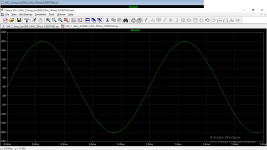
simulation using avtech's file shows
R5 (Pcb) or R17(in sim)= 15k makes both halves of the o/p nearly equal.
whereas 12k makes negative half clip earlier.
Attachments
Last edited:
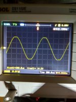
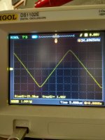
Ha ha i have just now put a 50K trimmer in R5 position and adjust for 25V o the mind point(+of the C10) now the clip is symmetrical but still at 14V. When input is 330mV.
What is the output voltage that simulation indicate when clip?
What is the output voltage that simulation indicate when clip?
Attachments
Last edited:
Ha ha i have just now put a 50K trimmer in R5 position and adjust for 25V o the mind point(+of the C10) now the clip is symmetrical but still at 14V. When input is 330mV.
What is the output voltage that simulation indicate when clip?
just about 20v with a 50 v supply and 0.45v input. these are peaks.
if you posted rms 14v, then your measurements match perfectly.
Last edited:
Aha BINGO!!!please see above edited post. If you are reporting rms values, then your measurments match up with sim. So amp will give 25W/8R, and in your case its giving 32W/6R.
It is as per spec. sorry for the confusion.
Simulation and real life in agreement!
Last edited:
A ok.i will ckeck this in the Morning.yes! perfect match of sim and actual, I have become a bit wiser with LT spice with this little exercise, thanks to avtech and you.... . please tell us what is the final trimmed R5 value you have presently.
Yes doctor pcb!#153,
wondering if Apex simple cap-mx can be useful here and other single supply amps.
Υou can not stop surprise us!!!
With quasi output stage, used here, you can never have ideal bias because upper driver/output pair (Darlington) requires different bias from the lower pair (Sziklai). It requires separate bias circuits for upper and lower pair. In the old times it was usual to set higher bias that suits upper pair. It's irrelevant weather you will use 10mA or 50mA because for optimum bias upper pair requires 200mA and lower 10mA.
Singleton input amps, like this one, are loved for it's specific distortion spectra. They have numerous fans.
Singleton input amps, like this one, are loved for it's specific distortion spectra. They have numerous fans.
Retro
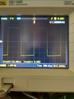
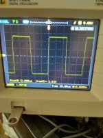
Crossover distortion visible.
This start to disappear at 14mA bias setting.
Crossover distortion visible.
This start to disappear at 14mA bias setting.
Attachments
Last edited:
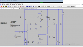
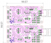
I found an older Mile's post at the local Serbian forum, where he gave a short explanation of AX6 circuit, and translated it. This is what he said:
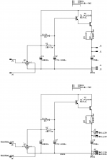
AX6 has two global feedback circuits, one DC circuit before series output cap that keeps output at the half of supply voltage, and second AC feedback circuit that is taken after the output cap to lower distortion produced by the cap. VAS transistor has local feedback using emiter resistor (220R) and 100uF cap. Input transistor is compensated with 47pF to prevent ingress of ultrasonic noise at the input of amp. 27R resistor at the emiter of 2SA1837 driver helps stabilizing bias current.
AX6 has two global feedback circuits, one DC circuit before series output cap that keeps output at the half of supply voltage, and second AC feedback circuit that is taken after the output cap to lower distortion produced by the cap. VAS transistor has local feedback using emiter resistor (220R) and 100uF cap. Input transistor is compensated with 47pF to prevent ingress of ultrasonic noise at the input of amp. 27R resistor at the emiter of 2SA1837 driver helps stabilizing bias current.
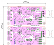
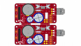
sch, stuffing guide, Diy pdfs and gerbers for the apex simple cap mx. untested.
regards
Prasi
regards
Prasi
Attachments
-
apex cap MX CU BTM.pdf46.1 KB · Views: 187
-
apex cap MX TOP SILK.pdf56.7 KB · Views: 167
-
GERBERS_CAP MX.zip523.7 KB · Views: 131
-
 apex cap-mx.png129.2 KB · Views: 340
 -
 apex cap-mx_sch.png8.5 KB · Views: 374
 -
 1.png512.4 KB · Views: 358
 -
 2.png272 KB · Views: 198
 -
 3.png239.5 KB · Views: 176
 -
 4.png507.4 KB · Views: 204
Spice file
I found some spare time to clean up the sim files.
Attached is a relabelled spice file that reflects the most recent schematic in terms of component designators. This should alleviate confusion between the sim and the schematic when refering to specific components.
This version has the output silicon that I am currently working on, so change these devices to match whatever you are using.
I am using a .step command for voltage input to find the clipping point as well as one set up for RBias to help with finding appropriate values. Set these to ;.step and reactivate the .param with your desired values once you have identified them.
----------------
Just for your viewing pleasure, I have also uploaded another version with gain set to around 25 and (I think) global feedback altered via R6. This drops the simulated THD from around 0.055 to 0.027.
This was done by reducing the 6k8 R6 to 3k6:
Gain = 1+(R6/R4) = 1+(3600/150) = 25.
Attachments
- Home
- Amplifiers
- Solid State
- Retro Amp 50W Single Supply