Hi -
After building a Leach low-TIM 6-channel amp back in '95, I have come up with several mods I would like to make but need some help/recommendations.
For a new set of amps (either the low-TIM for the 6 main speakers and the Superamp for the subs for each of the 6 channels and dedicated subs, or just all Superamps), I would like to add the following:
1. auto turn-on/off that is either signal-sensing, 12/24Vdc, or both
2. current inrush limiter
3. delay turn-on that is not in the signal path (could I somehow falsely trigger the protection circuit transistors with a delayed cut-off without turn-on thump?)
4. Clipping indicators (Dr. Leach did not have any ideas for an "accurate" method to monitor this when I was a student, although he mentioned something about the feedback path may somehow be affected when clipping occurs???)
I would like to use a heatsink(s) that will work on the inside of the chassis, probably run down either side from front to back, but can not find any good resources.
Thanks for any help.
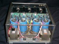
Included is a picture of the 6-channel amp I have enjoyed for the last 6 years.
After building a Leach low-TIM 6-channel amp back in '95, I have come up with several mods I would like to make but need some help/recommendations.
For a new set of amps (either the low-TIM for the 6 main speakers and the Superamp for the subs for each of the 6 channels and dedicated subs, or just all Superamps), I would like to add the following:
1. auto turn-on/off that is either signal-sensing, 12/24Vdc, or both
2. current inrush limiter
3. delay turn-on that is not in the signal path (could I somehow falsely trigger the protection circuit transistors with a delayed cut-off without turn-on thump?)
4. Clipping indicators (Dr. Leach did not have any ideas for an "accurate" method to monitor this when I was a student, although he mentioned something about the feedback path may somehow be affected when clipping occurs???)
I would like to use a heatsink(s) that will work on the inside of the chassis, probably run down either side from front to back, but can not find any good resources.
Thanks for any help.
Included is a picture of the 6-channel amp I have enjoyed for the last 6 years.
Attachments
My inrush limiter is a double-throw, center-off switch with a largish
six ohm power resistor in one leg. Throw switch to starting position and wait a couple of seconds, then throw to the run position. I'm charging a quarter-farad of capacitance, and it seemed prudent to do this.
Seal Electronics has a relay-driven board that will accomplish some of the things you want to do.
http://www.sealelectronics.com/kits/images/auxboard.jpg
Nifty chassis design! I've been building and using Leach's design since the late 70s and just upgraded my main amp to the ver 4.5
boards; very pleased with the sound.
Inrush Limiter
For inrush limiters, I suggest you take a look at the inrush limiter published in the June 1986 issue of the Elektor magazine under the 1KW power amp. It consist of a timer which allows the high inrush current to flow through a "brake-resistor" of 100 ohms or so and them shorts out the resistor by a relay about 2 to 3 seconds later. After that it senses whether theres any DC at the output and if everything is alright, it latches another relay to switch on the loudspeakers. If at anytime theres any DC at the amplifier output, it disconnects the speakers. I have built this circuit many times over in many projects and would have ended up with many fried speakers if not for this handy circuit. It is very easy and cheap to build and even the PCB layout is provided.
Strictly no turn-on and turn-off thumps from your speakers and a very effective protection against DC at your amp's output!
ckt
I fully agree with the above post of DIYMAN. It is a super reliable circuit that I have built many times over. It requires an additional transformer and you have to provide for a 12 volt supply separately, ie., it is not part of the PCB layout that DIYMAN is referring to, but tapped from the same transformer to drive the relays.
DC inrush protector
Hi Explorer,
Sorry! I did not notice your question earlier! I do not have a scanner and as such is unable to send you a picture of the schematic and PCB layout. I suggest you email Elektor as they sell photocopies of past articles at reasonable prices. Hope this helps.
ckt")
Hi Explorer,
Sorry! I did not notice your question earlier! I do not have a scanner and as such is unable to send you a picture of the schematic and PCB layout. I suggest you email Elektor as they sell photocopies of past articles at reasonable prices. Hope this helps.
ckt
- Status
- This old topic is closed. If you want to reopen this topic, contact a moderator using the "Report Post" button.