Michael Kiwanuka,
I have read your paper somewhat thoroughly: it is impeccably done, masterful. It was my impression while reading that the paper was very likely a Senior BSEE thesis: a well said synopsis stating the various industry problems, oversights, inaccuracies, delusions and wishful ignorances, followed by a careful expository building on Fairchild's original 'improved' limiter in ways to adapt to the actual complex-plane SOA of real-world output devices and reactive speakers. You did not eschew complexity, nor fall head-over-heels for simplicity. Balanced.
Very well done.
Yet, unless I just missed it, there appears not to be an adaptive clamp on output VI product based on a heatsink mounted set of thermistors or other thermal sensors. In the many decades of designing finals, I (or really "we") have noted that thermal sensors provide a "third dimension of limit", which is especially protective for commercial-grade power amplifiers employed at live-sound outdoor events. Very often, ambient temperature can exceed 40C, and with far less-than-optimal airflow through amplifier cabinets, 60C or higher so-called cooling air is remarkably frequently encountered.
Regardless of the source though, and conditions, it is advised and worthy to include such thermal-limit protection along with the SOA circuitry, I would think. Having such circuitry certainly impacts realizable output power, but "c'est la guerre"... sound engineers aren't supposed to accidentally fuze the amplifiers if they're overdriven relative to the ambient conditions.
If I missed your thermal-angle clamping, please refer me to the page(s) where that was addressed. If not, a comment or two would be welcome!
Again, bravo!
GoatGuy
Hello,
Thanks for your kind words.
I did mention in passing on pg 16 that an amplifier should have DC offset and thermal protection.
I didn't go into details in this regard as I thought those two facets of amplifier protection extraneous to SOA protection.
However, my general view is that thermal protection, rather than being linked to SOA protection, should be associated with the circuitry that disconnects the amplifier's output from the load. I think Douglas Self has discussed such a system in one or other of his books.
Regards,
Michael.
But the V change is in the supply rail and thus the NFB amp manages to ignore it (sufficiently) much like it ignores all the other (bigger) V changes that are on the supply rail.
But the heating of the fuse element will distort it and make it more fragile to later events and/or mechanical "shocks", even if initial pulses don't open it.
Probably.the heating of the fuse element will distort it and make it more fragile to later events
Look at the Krell Klone results to see how much the fuse can take and not blow, ~21Apk repeating through an F4A.
Normal music does not stress the fuse at anything like that level into the rated speaker impedance, both due to very short term transients and very few transients that get up to the maximum current capability.
I would say a pair of 5A fuses is more appropriate for a 100W into 8ohm amplifier.
Yes, this what I use in my 100 watter nx- Amp.
A overheated output stage can develop cross-conduction high enough to maintain it's high temperature. Disconnect from power supply or mains is probably better.... my general view is that thermal protection, rather than being linked to SOA protection, should be associated with the circuitry that disconnects the amplifier's output from the load....
Last edited:
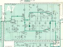
Wouldn't recommend it.Please analyze the following SOA concept used in old Tandberg TR1040.
Thank you, Victor
Yes sir , I Undersand .
Please , i'm interested in a mathematical example true circut protection SOA (universal) to protect the real world real output stage of a Class AB amplifier fed to
1) + / - 50 V with two pairs of transistors end power
2) + / 60 V end with three pairs of power transistors
3) + / - 70V with four pairs of power transistors end
4) + / - 85 V, with six pairs of power transistors end
5) + / - 100 V, with eight pairs of power transistors end
Heatsink will be in the worst case temperature 90 Cesius degrades due to optimum dimensioning and active cooling with fan brushless using transistors 2SA1943 end type / variant 2SC5200 or second choice MJL21194 / MJL 21193 (if needed number of transistor pairs final could be reduced by appropriate neccesary ), active duty with at least 60 degrees phase shift between the current through the load and tension.
Thanks in advance, Victor
Hi Victor,
Just read the article carefully from start to finish and you should be able to design your own SOA protection circuit without difficulty.
I suggest you buy the Texas Instruments TI-89 calculator to help you solve the simultaneous equations that arise. It's what I use.
Just read the article carefully from start to finish and you should be able to design your own SOA protection circuit without difficulty.
I suggest you buy the Texas Instruments TI-89 calculator to help you solve the simultaneous equations that arise. It's what I use.
This is great work, but for those of us who are less advanced in the calculations, such as Victor, we need a few more hints.
I've been reading it with the greatest interest, but I must admit I need a little bit more to be able to do it with confidence. I'm quite sure I'm not the only one. (ask Victor )
)
What I'm looking at is your fig. 33 on page 44, which is the closest to what I'm trying to calculate right now, which is exactly the topo used in the Leach amp.
The difference between your fig. 33 and that Leach amp arrangement, is the resistor between each protection transistors' base and emitter.
Leach has also added a few things, such as those caps and the diodes in reverse on those base/emitters as well, but those don't change the calculations.
I also noticed you don't add those diodes in the collectors, why?
I used to have one of those a long time ago, actually it was a TI-57, but although I still have it somewhere, it's definitely out of order.
I am trying to make a simple spreadsheet to make those calulations automatic and easy. I wanted to make this and share it, because many can also benefit from this.
I tried toying a bit with the one made by Jens Rassmussen, which is really great and he added other things such as the SOA chart. Very nice but not enough info to use it properly in all situations, and I'm still not certain to do things right.
I am also working on an other little project, in an other thread in the forums, with a 2N3055 based grounded bridge amp. I added the same protection circuitry as on the leach amp, so I need to calculate this right, but I want to do it in a way that I fully understand what I'm doing, and share the info and spreadsheet as well.
I get close with your very insightful explanations and examples, however the little difference loses me.
Just read the article carefully from start to finish and you should be able to design your own SOA protection circuit without difficulty.
I've been reading it with the greatest interest, but I must admit I need a little bit more to be able to do it with confidence. I'm quite sure I'm not the only one. (ask Victor
)What I'm looking at is your fig. 33 on page 44, which is the closest to what I'm trying to calculate right now, which is exactly the topo used in the Leach amp.
The difference between your fig. 33 and that Leach amp arrangement, is the resistor between each protection transistors' base and emitter.
Leach has also added a few things, such as those caps and the diodes in reverse on those base/emitters as well, but those don't change the calculations.
I also noticed you don't add those diodes in the collectors, why?
I suggest you buy the Texas Instruments TI-89 calculator to help you solve the simultaneous equations that arise. It's what I use.
I used to have one of those a long time ago, actually it was a TI-57, but although I still have it somewhere, it's definitely out of order.
I am trying to make a simple spreadsheet to make those calulations automatic and easy. I wanted to make this and share it, because many can also benefit from this.
I tried toying a bit with the one made by Jens Rassmussen, which is really great and he added other things such as the SOA chart. Very nice but not enough info to use it properly in all situations, and I'm still not certain to do things right.
I am also working on an other little project, in an other thread in the forums, with a 2N3055 based grounded bridge amp. I added the same protection circuitry as on the leach amp, so I need to calculate this right, but I want to do it in a way that I fully understand what I'm doing, and share the info and spreadsheet as well.
I get close with your very insightful explanations and examples, however the little difference loses me.
at least use a free ODF spreadsheet openOffice/officeLibre
Oh that's not where the problem is. I use excel and I even have access to mathcad once in a while too.
The key is to fully understand how to proceed and get it done right.
for more math functionality SciLab is a free MatLab workalike and has simple GUI templates
Octave is also free and open source, supposedly more compatable with matlab's m files
The main issue for me is that I'm on mac, so there are different choices. I only access a windows machine when needed, but as a matter of course I don't want to use windows if I don't have to.
I am working on making a spreadsheet. The writeup from Mike helps, but there are some intermediate results omitted that I am not yet able to figure out.
Yes, you could switch the rails - in fact it would probably be easier than the speaker. I have toyed with the idea but not organized my thoughts into a circuit yet.
I can't wait for this!!
- Status
- This old topic is closed. If you want to reopen this topic, contact a moderator using the "Report Post" button.
- Home
- Amplifiers
- Solid State
- Michael Kiwanuka's SOA PAper