Dadod, I think you use a regulated power supply? There is no need for a regulated power supply for power amps.
The idea I proposed is to have solid state switches in the unregulated supplies of the amp. to disconnect them from the amp. in the event of SOA violation or DC offset.
Yes it is a regulated but not with fix output voltage. It is more similar to capacitance multiplier, output follows slow input voltage changes. Capacitance multiplier doesn't need big capacitance bank and semicondactors are cheaper then big capacitors. Power dissipation lost on the regular is relatively small(needs no more then 5 V of voltage drop for proper funtion). Then it was quite easy to integrate all needed protection(it is not current limiter but current dependent current delayed fuse).
BR Damir
Has anyone considered SOA protection in which the protection transistors are removed from the forward path of the amplifier and, instead, opto-coupled to a bistable which drops out the output relay?
The protection locus would have to be conservative as it would have to accomodate the fact that it may take up to ten milliseconds to drop out the relay.
This is what I use; the actual activation of the relay is done through a uP7331 (IIRC the number).
jan
Attachments
Can those relays be used to turn off the supply rails instead of having them in series with the output?
I proposed to use opto-coupled trench FETs to isolate the power rails to the amp after I saw Andrew's solid state speaker relay.
Seems like an excellent idea for home audio.
- Protect the speaker and the amp with one circuit.
- No relays to fail or weld shut.
- No fuses to fail or replace.
- Eliminate any possibility of tedious debate about the effect of the FET in series with the speaker.
Didn't have much response, most people just reproduce the old speaker relay idea.
I plan to use this in my next amp.
Best wishes
David
Last edited:
I have already "tested" a prototype for the -ve supply rail. It uses Nchannel and is easily triggered with a two transistor Thyristor to latch it "OFF".
I have not worked up a +ve rail version that can use the same Nchannel device without a higher voltage +ve supply rail to give the Vgs across the switching N mosFET.
I have not worked up a +ve rail version that can use the same Nchannel device without a higher voltage +ve supply rail to give the Vgs across the switching N mosFET.
I have already "tested" a prototype for the -ve supply rail. It uses Nchannel and is easily triggered with a two transistor Thyristor to latch it "OFF".
I have not worked up a +ve rail version that can use the same Nchannel device without a higher voltage +ve supply rail to give the Vgs across the switching N mosFET.
Use photo-voltaic couplers to drive the FETS. Then you can use the better FETs in both rails.
Best wishes
David
This is what I use; the actual activation of the relay is done through a uP7331 (IIRC the number).
jan
Jan, you'll recall I simulated your triple slope protection arrangement and showed that it doesn't work as you intended.
Is the uP7331 latching? If it's not it will turn the relay on and off instead of dropping it out permanently untill power is cycled.
Jan, you'll recall I simulated your triple slope protection arrangement and showed that it doesn't work as you intended.
Is the uP7331 latching? If it's not it will turn the relay on and off instead of dropping it out permanently untill power is cycled.
Yeah I never was able to reconcile your sims with my build unit, which seems to follow the intended curve as far as I could measure.
That uP chip can be set to switch off and only switch on again as power is recycled (it has an AC power sensing also) or (with a jumper) to make it close the relay when the overload is no longer there, after a setable delay. That is the setting I normally use; I have it 're-try' every 2 secs or so.
jan
These MOSFET drivers look promising:
Data Sheet - ASSR-V621 and ASSR-V622, Dual Channel Photovoltaic MOSFET Driver (6.5V/15μA) (95 KB)
Data Sheet - ASSR-V621 and ASSR-V622, Dual Channel Photovoltaic MOSFET Driver (6.5V/15μA) (95 KB)
These MOSFET drivers look promising:
Data Sheet - ASSR-V621 and ASSR-V622, Dual Channel Photovoltaic MOSFET Driver (6.5V/15μA) (95 KB)
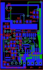
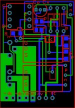
I have implemented and tested open circuit on full power 50V on 4 ohms with a short circuit on the 4 ohms, only a small spark on the shorting wire; Works great.
two circuits on switch (with pnp or npn logic and dc or ac capabilities) and one short circuit detector with latch
Attachments
Can you describe what your circuit is supposed to do and how it works?
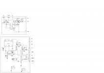
The top circuit in the schematic is a mosfet switch that can be used in serie in each power supplies (+/-) of the amplifier. It is also able to swich AC signals, then two mosfets are used. pnp or npn command can be used.
The bottom circuit uses an IC that transforms ( by hall efffect) current in analog voltage. This Ic has a preset current value that will operate the fault output pin and will latch it until 5v is reset. An Ipeak output is operated by the comparators if a current value preset by the comparator résistors is crossed. This output is not latched.
The circuit is used as a short circuit detector at the output of an amp and drives the mosfet switch circuit described above to open the dc power supply. Ipeak is also sent to a supervising microcontroller to activate a monitoring led
Then it was quite easy to integrate all needed protection(it is not current limiter but current dependent current delayed fuse).
BR Damir
I wouldn't depend on a fuse for SOA protection.
I wouldn't depend on a fuse for SOA protection.
It is electronic fuse, look the schematic, Q6 and Q106 are the current sensors and C3 and C103 define the current dependent dalay to triger CSRs formed with Q8, Q9 and Q108, Q109.
BR Damir
Attachments
standard IV limiting for DC or 100ms temperature de-rated SOAR works well.I wouldn't depend on a fuse for SOA protection.
A modified version of this IV limiting is required to allow short term transients to pass without early triggering where considerably more SOAR is available for 1us to 10ms transients.
Fuses in the supply rails, however, are very good for long term DC limiting exceeding say around a second.
I would use a a pair of F2.5A for a 100W into 8ohms capable amplifier and these fuses will pass a single event 10ms transient of at least 20Apk (4 times the peak current into a 8r0 load) and even more for <1ms repeated event transients.
These fuses will pass a continuous bass frequency for many seconds that has an rms value of ~2.5A and I have never blown them with any music signal into 8ohms speaker.
I would say a pair of 5A fuses is more appropriate for a 100W into 8ohm amplifier.
I tested my Krell Klone KSA100 for maximum power just into clipping with F4A in the power supply leads. This gave out maximum powers of ~110W into 8r0, ~210W into 4r0 and ~400W into 2r0. My report was posted many years ago.
Similarly My Leach clone using a slightly lower fuse showed ~170W into 8r0 and ~310W into 4r0.
In neither case did the fuses blow. Part of the reason is that the rail fuses are working at 50% duty factor. The other is that the peak current is for a fairly short proportion of the waveform cycle. Fuses can pass many times their rated current for short periods.
This advantage applies even more when music is being reproduced. The transients are of very short duration, if and when they approach the peak currents that an amplifier can pass.
I could recommend even lower fuses for domestic audio reproduction than F2.5A for 100W into 8ohms speaker, but there is an increased risk of one rail fusing and sending a DC to the speaker. Extra protection must be fitted to ensure both rail fuses blow nearly simultaneously to avoid DC to the speaker for most amplifiers.
Michael Kiwanuka,
I have read your paper somewhat thoroughly: it is impeccably done, masterful. It was my impression while reading that the paper was very likely a Senior BSEE thesis: a well said synopsis stating the various industry problems, oversights, inaccuracies, delusions and wishful ignorances, followed by a careful expository building on Fairchild's original 'improved' limiter in ways to adapt to the actual complex-plane SOA of real-world output devices and reactive speakers. You did not eschew complexity, nor fall head-over-heels for simplicity. Balanced.
Very well done.
Yet, unless I just missed it, there appears not to be an adaptive clamp on output VI product based on a heatsink mounted set of thermistors or other thermal sensors. In the many decades of designing finals, I (or really "we") have noted that thermal sensors provide a "third dimension of limit", which is especially protective for commercial-grade power amplifiers employed at live-sound outdoor events. Very often, ambient temperature can exceed 40C, and with far less-than-optimal airflow through amplifier cabinets, 60C or higher so-called cooling air is remarkably frequently encountered.
Regardless of the source though, and conditions, it is advised and worthy to include such thermal-limit protection along with the SOA circuitry, I would think. Having such circuitry certainly impacts realizable output power, but "c'est la guerre"... sound engineers aren't supposed to accidentally fuze the amplifiers if they're overdriven relative to the ambient conditions.
If I missed your thermal-angle clamping, please refer me to the page(s) where that was addressed. If not, a comment or two would be welcome!
Again, bravo!
GoatGuy
- Status
- This old topic is closed. If you want to reopen this topic, contact a moderator using the "Report Post" button.
- Home
- Amplifiers
- Solid State
- Michael Kiwanuka's SOA PAper