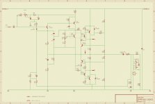
R36, R37 and C22 form a boot-strapped resistor load. A simple resistor to ground would make this a very low open-loop gain design.
Probably a bootstrapped resistor if all the active devices are accounted for.
hi,
I have decided the next task is for me to apply values to the discretes, I had already replaced a couple of resistors and undertaken a visual check and "tapped" the electrolytic tops (digital interference") ).
).
The lack if values is probably causing unnecessary hassle.
cheers for interest and help
..
..
I have decided the next task is for me to apply values to the discretes, I had already replaced a couple of resistors and undertaken a visual check and "tapped" the electrolytic tops (digital interference
). The lack if values is probably causing unnecessary hassle.
cheers for interest and help
..
..
I think there are some errors to pick up first.
Many thanks for taking a look. I regret that there maybe quite a few errors yet to come on my part.
I was lazy on the output interface section, but have now traced it correctly. There were a quite a few wirelinks on the pcb and some crossing over to achieve the correct channel orientation (L/R) on the headphone output. Also thought had gone into trying to reduce crosstalk etc by trying to keep signal paths at R_angles....
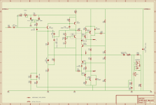
I have put some values in, this should also help me in marrying up the modules better. Am about to map the caps and add the tone control section.
Thanks again guys.
Attachments
Not sure what the ultimate goal is though
To be honest I think it has blurred a little, after repairing it I was hoping to set and restore this amp up as best I can, there is no schema so I have had to create one and also for me to learn something on the way.
I am sure there is some component fatigue, values drifting etc. I have some clipping on the negative sine at ~ 3/4 volume, I understood this to possible be uneven bias, but I was not altogether sure which components formed the bias.
I am also not sure where to set the settings of the preamp, is this on the knee? I also tried to establish the voltage that should be on the output terminals under different conditions.
I am half toying with the idea of taking an old design and updating with modern PCB technology maybe 4 or more layers and surface mounts etc etc. Every book seems to offer similar designs and not much seems to change over the years, Spice seems to be a path that is popular but is maybe only for minor tweaking and theoretical discussion. There are some transistors with increased bandwidth that are available now that were not when the amp was built, I am not sure that their performance in the audio sense are that much improved.
The pcb is single layer through hole laid out with letraset and I can "see" it is as noisy as notting hill carnival.
Maybe I can use modern pcb technology to offer a greater improvement to what could be a valid and currently acceptable amplifier design.
..
The clipping (assuming its not in the preamp... very unlikely) could be due to the output not being biased to the "mid point" or it could be the amp running out of current delivery on the negative half cycle. Or, the protection circuitry cutting in. All are easy to check. I would try it with a much higher load resistor or even non at all. If the bias is wrong the amp will still clip just the same. Are both channels the same ?
Different transistors won't alter the basic performance of the amp to any real degree. I suppose theoretically that higher gain devices and output devices that hold up better under high current drive could decrease overall distortion but its very much sweating the small numbers and no real practical gain. The bandwidth is determined by the passives as much as anything although there could be some merit in using more modern output devices.
Spice is a very useful tool when used properly.
The clipping (assuming its not in the preamp... very unlikely) could be due to the output not being biased to the "mid point" or it could be the amp running out of current delivery on the negative half cycle. Or, the protection circuitry cutting in. All are easy to check. I would try it with a much higher load resistor or even non at all. If the bias is wrong the amp will still clip just the same. Are both channels the same ?
Thanks for advice, I will perform each stage in turn.
I agree, furthermore it is my suggestion that layout using miniature devices and layering (power,signal,ground planes) could make more improvement than swapping up transistors as is.Different transistors won't alter the basic performance of the amp to any real degree. I suppose theoretically that higher gain devices and output devices that hold up better under high current drive could decrease overall distortion but its very much sweating the small numbers and no real practical gain. The bandwidth is determined by the passives as much as anything although there could be some merit in using more modern output devices.
I guess my reservation is that it depends on detailed device models. you get out what you put in... rubbish in = rubbish out. Spice has come a little late for me, I have looked at them.. and in particular Qucs but I have a way to go getting it set up sufficiently to give any useful output.Spice is a very useful tool when used properly.
thanks again.
cheers
..
Its hard to say regarding a new layout and PCB. Ground planes aren't always appropriate to audio, more to RF really. Get the grounding layout correct and "wires and their effects" literally disappear. Same for PCB print. A ground plane gets you 85% of the way there but then you can't improve or route grounds differently. Even an unetched copper clad PCB has significant resistance and if you took several random points and applied current into each then there would still be very measurable potential differences across the board... all interacting with each other. With carefully applied conventional wiring and grounding you can arrange it so that anything carrying current can not interact with anything else.
I understand what you are saying, an 18"x 9" pcb has enough room to allow space for reduction of interference even with through hole devices, i guess also gives improved thermal properties compared to compact population. I will rethink this.... thanks for the observations.
maybe later on today I will have the chance to get the amp opened up on the bench and have a prod about......
cheers
..
maybe later on today I will have the chance to get the amp opened up on the bench and have a prod about......
cheers
..
The 2200uF O/P capacitor is a clue that this is an 8 Ohm speaker design. Most modern speakers are 4 Ohm, so this amplifier must be used with the right load
the dummy load I use is a pair of 50w 8r2 mounted on a big heatsink and a pair of infinity rs2000 measured impedance of 6ohm at the workbench.
The main speakers are spendor sp1's which are 8ohm, incidentally at this recent 16th party the voice coil tails in the coles 4001 super tweeters fractured on both speakers, so they are disassembled and waiting to be repaired. I intend to cut back and solder the 36awg magnet wire and then dip in some conformal coating that I have on the shelf, or maybe I should lacquer them?. Anyway if I am unsuccessful Coles have recently started production again and I will have to replace them.
thanks for help
cheers
..
Do not seem to be having much luck at present, workshop equipment failing at an alarming rate... seems to be an endless cycle of repairing equipment that is needed to repair other kit.The remaining capacitor values?
anyway here are some cap values
cheers.
..
Attachments
- Status
- This old topic is closed. If you want to reopen this topic, contact a moderator using the "Report Post" button.
- Home
- Amplifiers
- Solid State
- Reverse engineering a John Widgery Sondex/Radford SS amplifier.