About C1/R18 && R13/C5 (0.1R + 100uf) in the PSU part.
Could I use other value of the resistor? 0.22 0.47 0.68 1 ? Does the capacitor need to change along if it is a yes?
You can use 0.22R or two of them parallel, but not higher values. No need to change the capacitor.
I suggest to read this thread, there is some improvement of this shunt regulator valid for the GainWire mk2 too. http://www.diyaudio.com/forums/power-supplies/286425-shunt-regulator-15v-6.html#post4621345
Thanks! I did read the thread and applied some of the improvement on PSU and trying to increase current on the buffer right now. BTW, could I use 0.1R with 220u instead of 100u?
Thanks! I did read the thread and applied some of the improvement on PSU and trying to increase current on the buffer right now. BTW, could I use 0.1R with 220u instead of 100u?
Yes, the cap value is not critical, just low ESR will produce peaking im MHz region, that's way low value resistor was added in series.
Yes, the cap value is not critical, just low ESR will produce peaking im MHz region, that's way low value resistor was added in series.
Thanks, I got it.
Good day Dadod,just letting you know that all the pcb's have arrived.Thank you and best regards,Manuel
You welcome Manuel.
Hello Damir
Questions :
If I understand correctly value of the R44 and R45 = 4R7 isn't critical , and 5 Ohm ( two 10R parallel ) should not influence THD ?
How about R17 and R46 = 6R8 ? You used preliminary 10R ?
What is the acceptable range of the resistance value ?
The Q21 with Q1 and Q5 forms a Wilson current mirror, right ?
Is the any optimal parameters (Vbe, hfe ) for Q21 in correlation to the strongly matched Q1 and Q5 or it doesn't matter ??
Hello Damir
Questions :
If I understand correctly value of the R44 and R45 = 4R7 isn't critical , and 5 Ohm ( two 10R parallel ) should not influence THD ?
How about R17 and R46 = 6R8 ? You used preliminary 10R ?
What is the acceptable range of the resistance value ?
The Q21 with Q1 and Q5 forms a Wilson current mirror, right ?
Is the any optimal parameters (Vbe, hfe ) for Q21 in correlation to the strongly matched Q1 and Q5 or it doesn't matter ??
I prefer that you use 4R7 and 6R8 values. I chose those values for lowest distortion in simulation.
Q21, Q22 are not critical, resistors R20, R21 has been chosen for best current mirroring.
The current mirrors resistors R5, R14, R6, R16 should be of 0.1% tolerance.
Can you give us general instruction for matching transistors, which one for hfe, Vbe or maybe both (in resonable tolerances).
Transistors to be Vbe/hfe matched:
Q11/Q12, Q3/Q4, Q15/Q16, Q13/Q14, Q9/Q10, Q6/Q8
Transistors to be hfe matched:
Q1/Q5, Q2/Q7
It is not very critical, DC servo will compensate for the DC offset, but with better matching THD is going to be lower.
Remember that critical parts are R5, R14, R6, R16, to be 0.1% or if you can't find that and have enough precise ohmmeter then you can choose 0.1% pars from 1% resistors, R5/R6 and R14/R16(apsolute value is not so important just to be less then 0.1% difference in those resistors pairs.
Already did resistors matching but transistors requires much more effort.
I have some hfe matched (with roughly 2mA colector current) and now I will run these thru vbe matching to see how it goes. I was thinking about circuit in this link http://cappels.org/dproj/xstrmatch/Transistor_matching.html but maybe you have some better suggestion.
I have some hfe matched (with roughly 2mA colector current) and now I will run these thru vbe matching to see how it goes. I was thinking about circuit in this link http://cappels.org/dproj/xstrmatch/Transistor_matching.html but maybe you have some better suggestion.
Already did resistors matching but transistors requires much more effort.
I have some hfe matched (with roughly 2mA colector current) and now I will run these thru vbe matching to see how it goes. I was thinking about circuit in this link Transistor_matching but maybe you have some better suggestion.
I think I've showed transistors matching schematic in this thread already.
Hi Damir, that's really some cool work! I think it's time for me to try some CFAs. But I got some question about the matching of transistors in this topology. Indeed, without differential pairs it's not that urgent to match the bjts, but will it also be positive for the distortion figures? I got some THAT340 at disposal, really low noise, matched to 4% hfe(Err Anyone with matching device can do better than this). I'm looking forward to scale down the board with SMDs and double layer pcb, which can make specs better as well.
Hi Damir, that's really some cool work! I think it's time for me to try some CFAs. But I got some question about the matching of transistors in this topology. Indeed, without differential pairs it's not that urgent to match the bjts, but will it also be positive for the distortion figures? I got some THAT340 at disposal, really low noise, matched to 4% hfe(Err Anyone with matching device can do better than this). I'm looking forward to scale down the board with SMDs and double layer pcb, which can make specs better as well.
To match the same type is no big problem, but to have good match of the NPN/PNP is not so easy, mostly due Vbe difference. Better match will lower distortion and easy DC servo work, but it's not overly critical.
To match the same type is no big problem, but to have good match of the NPN/PNP is not so easy, mostly due Vbe difference. Better match will lower distortion and easy DC servo work, but it's not overly critical.
HI Damir, thank you for your reply! It surprised me a little that this circuit requires Vbe match.....Hfe match between complementary tubes within 1% is practical, but i havent noticed the Vbe consistency

And it occured to me that the output buffer can simply utilize a LME49600, saves place and really good distortion figure.
Last edited:
HI Damir, thank you for your reply! It surprised me a little that this circuit requires Vbe match.....Hfe match between complementary tubes within 1% is practical, but i havent noticed the Vbe consistency
And it occured to me that the output buffer can simply utilize a LME49600, saves place and really good distortion figure.
TI does not tell distortion in stand alone, just in combination with LME49710 with global NFB. Actually we don't know distortion figure of the LME49600.
My idea was to have non GNFB circuit, possibility to use it as CFA too was introduced later during development.
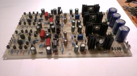
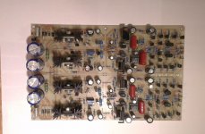
I have one finished GainWire mk2 board. It was used in my setup, but now I don't need it as I am going to balanced mk3 version. If someone interested to buy it PM to me.
This is stereo board with power supply(shunt) with possibility to choose between CFA mode and NGNFB mode with just two jumpers(stereo).
All you need to add are one 30VA 2x15V AC transformer and volume control with input selection.
Damir
This is stereo board with power supply(shunt) with possibility to choose between CFA mode and NGNFB mode with just two jumpers(stereo).
All you need to add are one 30VA 2x15V AC transformer and volume control with input selection.
Damir
Attachments
- Status
- This old topic is closed. If you want to reopen this topic, contact a moderator using the "Report Post" button.
- Home
- Amplifiers
- Solid State
- No NFB line amp (GainWire mk2)