This is no NFB line preamp with very low distortion and constant signal/noise ratio at all volume levels. In this thread http://www.diyaudio.com/forums/solid-state/235500-simple-line-buffer.html I showed output buffer I am using for this lineamp, and decided to put it in the Solid State thread instead in the Analog Line Level thread where is my first pre/headphone amp http://www.diyaudio.com/forums/analog-line-level/223835-current-conveyor-voltage-amplifier.html. I have had very good suggestion from keantoken for that preamp and I hope more will come here for this new one.
Charles Hansen wrote about his KX-R
"We simply use a variable resistance instead of a fixed resistance. Changing the value of the resistance changes the gain of the circuit. With a variable-gain circuit there is no input attenuator, as is normally found in a preamplifier. This brings about several advantages: The input impedance is not restricted by the value of the volume control (input attenuator). I mentioned that with conventional attenuators, the frequency response can vary with volume. In contrast, the KX-R has an input impedance of 1M ohm per phase, and the frequency response goes out past 250kHz regardless of volume setting. Another benefit is that the signal path is simplified, and there are fewer switches in the way. -------
"With VGT, the signal/noise ratio is constant regardless of the volume setting. A typical listening level might be 20dB below full gain, which translates into an effective increase in S/N ratio of 20dB.”
Similar advantages come with my pream, but off course I do not claim anything close to the KX-R.
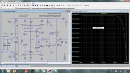
This preamp uses only BC550/560 transistors, nothing exotic or unobtainable. The core of the preamp is a current conveyor plus output buffer. As this current conveyor is very sensitive to the output load it is very important to have an output buffer with very low distortion and easy to drive input.
P1 in the schematic is the volume control and could use step attenuator as this one. Valab 23 Step Attenuator Potentiometer 10K Stereo Log | eBay
Damir
GainWire mk2 with higher output bias current suitable for low impedance headphones is here: http://www.diyaudio.com/forums/solid-state/235695-no-nfb-line-amp-gainwire-mk2-97.html#post4629715
Matching http://www.diyaudio.com/forums/solid-state/235695-no-nfb-line-amp-gainwire-mk2-99.html#post4669051
Charles Hansen wrote about his KX-R
"We simply use a variable resistance instead of a fixed resistance. Changing the value of the resistance changes the gain of the circuit. With a variable-gain circuit there is no input attenuator, as is normally found in a preamplifier. This brings about several advantages: The input impedance is not restricted by the value of the volume control (input attenuator). I mentioned that with conventional attenuators, the frequency response can vary with volume. In contrast, the KX-R has an input impedance of 1M ohm per phase, and the frequency response goes out past 250kHz regardless of volume setting. Another benefit is that the signal path is simplified, and there are fewer switches in the way. -------
"With VGT, the signal/noise ratio is constant regardless of the volume setting. A typical listening level might be 20dB below full gain, which translates into an effective increase in S/N ratio of 20dB.”
Similar advantages come with my pream, but off course I do not claim anything close to the KX-R.
This preamp uses only BC550/560 transistors, nothing exotic or unobtainable. The core of the preamp is a current conveyor plus output buffer. As this current conveyor is very sensitive to the output load it is very important to have an output buffer with very low distortion and easy to drive input.
P1 in the schematic is the volume control and could use step attenuator as this one. Valab 23 Step Attenuator Potentiometer 10K Stereo Log | eBay
Damir
GainWire mk2 with higher output bias current suitable for low impedance headphones is here: http://www.diyaudio.com/forums/solid-state/235695-no-nfb-line-amp-gainwire-mk2-97.html#post4629715
Matching http://www.diyaudio.com/forums/solid-state/235695-no-nfb-line-amp-gainwire-mk2-99.html#post4669051
Attachments
Last edited:
This is all saleman's babble.
What's news?
Said passive volume control is made out of fixed R19 and variable P1.
What's news?
")
We have the exact equivalent of a 3K5 volume pot, which can't go up to "10" but, say, "7" or "8" , depending on taper.
What's news?
1M input impedance? No switches?
Why not? Designer's choice, like anywhere else.
the signal/noise ratio is constant
effective increase in S/N ratio of 20dB
You contradict yourself within the same phrase
Take your pick, red or blue?
You can't have both at the same time
Ok, why use so many words to say "volume control potentiometer""We simply use a variable resistance instead of a fixed resistance. Changing the value of the resistance changes the gain of the circuit.
What's news?
There is no variable-gain circuit in that schematic, just 2 fixed gain blocks with a standard passive resistive attenuator, a.k.a "volume pot" between them.With a variable-gain circuit there is no input attenuator, as is normally found in a preamplifier.
Said passive volume control is made out of fixed R19 and variable P1.
What's news?
Same hereI mentioned that with conventional attenuators, the frequency response can vary with volume.
We have the exact equivalent of a 3K5 volume pot, which can't go up to "10" but, say, "7" or "8" , depending on taper.
What's news?
Here we just have 2 fixed gain blocks with a passive volume pot (or stepped attenuator, same thing) between them.In contrast, the KX-R has an input impedance of 1M ohm per phase, and the frequency response goes out past 250kHz regardless of volume setting. Another benefit is that the signal path is simplified, and there are fewer switches in the way.
1M input impedance? No switches?
Why not? Designer's choice, like anywhere else.
Absolute nonsense."With VGT, the signal/noise ratio is constant regardless of the volume setting. A typical listening level might be 20dB below full gain, which translates into an effective increase in S/N ratio of 20dB.”
the signal/noise ratio is constant
effective increase in S/N ratio of 20dB
You contradict yourself within the same phrase
Take your pick, red or blue?
You can't have both at the same time
I think you meant to say 'no global NFB'. It has gobs of local NFB in most stages.
Off course there is no amp without any negative feedback.
This is all saleman's babble.
Ok, why use so many words to say "volume control potentiometer"
What's news?
There is no variable-gain circuit in that schematic, just 2 fixed gain blocks with a standard passive resistive attenuator, a.k.a "volume pot" between them.
Said passive volume control is made out of fixed R19 and variable P1.
What's news?
Same here
We have the exact equivalent of a 3K5 volume pot, which can't go up to "10" but, say, "7" or "8" , depending on taper.
What's news?
Here we just have 2 fixed gain blocks with a passive volume pot (or stepped attenuator, same thing) between them.
1M input impedance? No switches?
Why not? Designer's choice, like anywhere else.
Absolute nonsense.
the signal/noise ratio is constant
effective increase in S/N ratio of 20dB
You contradict yourself within the same phrase
Take your pick, red or blue?
You can't have both at the same time
First, those words were from Charles Hansen about his Ayre KX-R preamp and, maybe a bit on salesman side but correct, sorry if I was not clear about it.
There is no "volume control potentiometer" and the gain is defined by P1/R9 ratio and it means there is variable gain circuit.
The signal/noise ratio is constant. When gain is down by 20 dB the noise is down by 20dB and in the same time output signal is down by 20dB, so signal/noise ratio is constant. Maybe that Hansen was not exactly correct.
Damir
Not quite true. It is just about possible to make fairly linear circuits without NFB, by exploiting the exponential behaviour of BJTs. No good reason to avoid NFB for audio though.dadod said:Off course there is no amp without any negative feedback.
Hi Damir,Here is the same preamp with different output buffer.
the usual performance from you ...
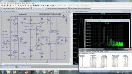
. Nice to see that this is possible without global NFB.Do you know which stage does create most distortion? Is it Q3/Q4?
How does the output buffer perform with lower load impedance?
There appear to be some subtle loops in the current mirrors. Are there any stability issues?
Kind regards,
Matthias
Hi Damir,
the usual performance from you ...
Do you know which stage does create most distortion? Is it Q3/Q4?
How does the output buffer perform with lower load impedance?
There appear to be some subtle loops in the current mirrors. Are there any stability issues?
Kind regards,
Matthias
Hi Matthias,
Thanks for your comment.
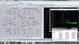
The current conveyor(gain block) has quite low distortion, main problem was to find suitable output buffer as the current conveyor is sensitive to the load. That is way I tried two types of the output buffer.
It may look that an amp with no GNFB should not oscilate, it is not so. C2 and R19 are here to stabilize the amp, as it should work with long cable, means capacitans. I simulate up to 1nF. This line amp could work very good with 1kohm of load but is better to keep it greater then 5kohm. Other output buffer neads own compensation too(C3/R27, C8/R28).
My other line amp(link in the first post) works excellently with 300ohm headphones, and I used it every day now.
When I designed this line amp the goal was to use easy obtainable and cheap transistors.
Best regards
Damir
Damir, you should try to use a zobel filter at the output buffer instead of the output resistor. There are several disadvantages with that resistor. Another way is compensation by using a RC network from the output to the input of the buffer. This will probably give the best results.
Damir, you should try to use a zobel filter at the output buffer instead of the output resistor. There are several disadvantages with that resistor. Another way is compensation by using a RC network from the output to the input of the buffer. This will probably give the best results.
Thanks manso,
Could you explain what disadvantages with output resistor? Similar resistor is normaly used to prevent an OPA to oscilate with capacitive load.
I tried different ways to compensate and used compensation worked well in the simulation.
I will try your zobel and RC suggestion.
Damir
Loss of bandwith, slewrate and output impedance is increased.
I dont know why Opamp manufacturers dont suggest the use of zobel networks, these have the disadvantage that the zobel should be tuned to cancel the effect of the capacitive load, the problem being the use of different loads requiring different zobel characteristics for optimal stability.
I dont know why Opamp manufacturers dont suggest the use of zobel networks, these have the disadvantage that the zobel should be tuned to cancel the effect of the capacitive load, the problem being the use of different loads requiring different zobel characteristics for optimal stability.
Damir, you should try to use a zobel filter at the output buffer instead of the output resistor. ......... Another way is compensation by using a RC network from the output to the input of the buffer. This will probably give the best results.
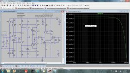
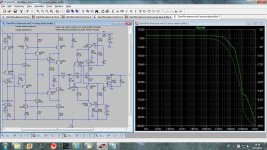
Here is gain simulation with your suggestion and indeed it works, but with a bit higher distortion at 20kHz. Could be that my values are not the best.
Thanks Damir
Attachments
One would expect that R19 already does sufficiently isolate the first stage from buffer and capacitive load. Nevertheless, you include C2 and additionally change it from 47p to 10p in the version with cascoded buffer. Why is C2 necessary?C2 and R19 are here to stabilize the amp, as it should work with long cable, means capacitans. I simulate up to 1nF.
Matthias
I would not disconnect compensation of the cascodes.Here is gain simulation with your suggestion and indeed it works, but with a bit higher distortion at 20kHz. Could be that my values are not the best.
Thanks Damir
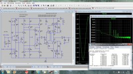
What are these resonances at about 20MHz and 100MHz? Do they already appear without the buffer?
Matthias
Hi Damir,
the usual performance from you ...
Kind regards,
Matthias
The Shoe Is The Sign - The Beginning - YouTube
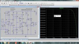
One would expect that R19 already does sufficiently isolate the first stage from buffer and capacitive load. Nevertheless, you include C2 and additionally change it from 47p to 10p in the version with cascoded buffer. Why is C2 necessary?
Matthias
Hi Matthias,
Here is the gain plot without output buffer. First one is without C2 and second with C2.
BR damir
Attachments

Holy grail! And Cheers!
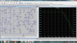
Here is gain simulation with your suggestion and indeed it works, but with a bit higher distortion at 20kHz. Could be that my values are not the best.
Thanks Damir
Interesting, some performance is lost. Can it be made stable if you remove the zobel and only the RC in place ??
- Status
- This old topic is closed. If you want to reopen this topic, contact a moderator using the "Report Post" button.
- Home
- Amplifiers
- Solid State
- No NFB line amp (GainWire mk2)