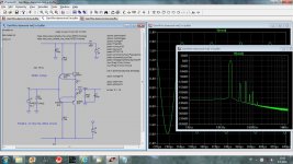
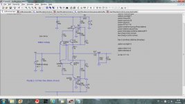
This is simple line buffer with the quite low distortion. I tried to connect it as a diamond buffer but it worked better in this way. I am not sure how it works but in simulation it works. Output impedance is 110ohm and it's good to drive 10kohm or higher loads. Any comments.
dado
dado
Attachments
one question may be if human ears/brain may discriminate such a difference and the other will be that you are only a quarter of the way there .
Meaning that simulation results is just an indication ...this buffer and others will be power supply depending, of course pcb depending , and of course properly matched devices depending
There might be some use after constructed and properly debugged .
This sounds like some integrated Pioneer amplifier spec sheet which very clearly says amplifier distortion 0.013% ( for example ) and while the statement is absolutely real in practice the reference is a game of words and refers to the amplifier only ....well the machine is an integrated amplifier and this number is of no practical use since this machine will work together with preamplifier and source selectors so distortion will never make it t this number ...
So yes ...its attractive but incomplete
Kind regards
Sakis
The bootstrapping of the input transistor's C's eliminates their Early effect, and a contribution to non-linearity.This is simple line buffer with the quite low distortion. I tried to connect it as a diamond buffer but it worked better in this way. I am not sure how it works but in simulation it works. Output impedance is 110ohm and it's good to drive 10kohm or higher loads. Any comments.
dado
Bootstrapping all 4 transistors should make a real difference: THD is not additive, and removing one of the sources only reduces the level by ~√2, which is more or less in line with what you observe
So yes ...its attractive but incomplete
Kind regards
Sakis
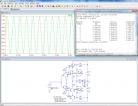
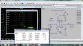
This is going to be output of the gain block, the one with very low distortion and this output buffer should not spoil to much that.
The gain block with no NFB and with distortion on the level of the 1ppm.
dado
I've seen a similar thing called a bootstrapped diamond buffer on this forum and it's quite common/popular. However that circuit 'crosses' the input transistor collectors to the opposite output transistor emitter. See post #1 here for example:
http://www.diyaudio.com/forums/analog-line-level/203908-output-inductor.html
From memory, Scott Wurcer used that output stage in his recent discrete opamp design, though I'm about to run out of battery so you'll have to search that yourselves. As I said, a few others have used the same circuit as well.
I'm not sure whether they had a good reason to 'cross' the collectors though. Maybe it's simply that no-one ever thought of your way.
Each pair of transistors looks like a Baxandall super-pair :
http://www.diyaudio.com/forums/solid-state/25172-baxandall-super-pair.html
It is better known to give high output impedance at the collector of the second transistor.
http://www.diyaudio.com/forums/solid-state/25172-baxandall-super-pair.html
It is better known to give high output impedance at the collector of the second transistor.
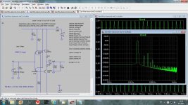
As expected, bootstrapping all 4 does make a significant difference.
In addition, it also pushes the input impedance to more than 200 megohm.
BTW, harmonic is almost pure second meaning it is caused mainly by imperfect complementarity of the transistors, not an intrinsic flaw of the topology.
In addition, it also pushes the input impedance to more than 200 megohm.
BTW, harmonic is almost pure second meaning it is caused mainly by imperfect complementarity of the transistors, not an intrinsic flaw of the topology.
Attachments
Last edited:
As expected, bootstrapping all 4 does make a significant difference.
In addition, it also pushes the input impedance to more than 200 megohm.
BTW, harmonic is almost pure second meaning it is caused mainly by imperfect complementarity of the transistors, not an intrinsic flaw of the topology.
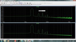
Thanks Elvee for your suggestion.
I put it even father and now distortion at 20kHz is 0.000002%.
I am going to use one of those buffers in my lineamp(no NFB) and I am not sure if the complexity is to much as the gain block is in 1ppm region. Could be that simpler version of the buffer is good enough.
Damir
Attachments
-120dB is 1ppm.
Your sim is predicting in the tens of ppb.
1ppm is distortion of the preceding gain block not of this buffer.
That is the kind of problem you be must be prepared for when using bootstrapping and similar schemes. Can you show the exact circuit in which it oscillated?I've found that elvee-dado buffer oscilate when used as output for my gain block,
BTW, shouldn't you tie the collectors of the input transistors to the higher potential, like in my version? This should give them more E-C space to breathe correctly

That is the kind of problem you be must be prepared for when using bootstrapping and similar schemes. Can you show the exact circuit in which it oscillated?
BTW, shouldn't you tie the collectors of the input transistors to the higher potential, like in my version? This should give them more E-C space to breathe correctly
Hi Elvee,
I will show the lineamp where I put this buffer, later in separate thread. It is a current conveyour.
I tried your circuit first and then did the changes step by step and each one lowered distortion a bit, cascode boostrap first and then cross connection of collectors to the opposite emitter resistors.
I had the same stability problem with your circuit as with this one.
dado
That is the kind of problem you be must be prepared for when using bootstrapping and similar schemes. Can you show the exact circuit in which it oscillated?
Here is the link to the complete circuit.
http://www.diyaudio.com/forums/solid-state/235695-no-nfb-line-amp-gainwire-mk2.html#post3485296
- Status
- This old topic is closed. If you want to reopen this topic, contact a moderator using the "Report Post" button.
- Home
- Amplifiers
- Solid State
- Simple line buffer