Hi and thank you All for the very interesting 3D ")
May i ask you which are the main benefits of the simmetrical arrangement ?
A single pair would measure significantly worse ?
I have in mind this kind of circuits to buffer the signal after a pot for line stage duties.
Very interesting 3D.
Thanks, gino
May i ask you which are the main benefits of the simmetrical arrangement ?
A single pair would measure significantly worse ?
I have in mind this kind of circuits to buffer the signal after a pot for line stage duties.
Very interesting 3D.
Thanks, gino
Last edited:
Hi and thank you All for the very interesting 3D
May i ask you which are the main benefits of the simmetrical arrangement ?
A single pair would measure significantly worse ?
I have in mind this kind of circuits to buffer the signal after a pot for line stage duties.
Very interesting 3D.
Thanks, gino
That buffer was intended to drive low ohmic headphones. For lineamp only, you can use simpler buffer as this here in the beginning of this thread http://www.diyaudio.com/forums/solid-state/225255-jlh-buffer-homage-john-linsley-hood.html, or you can use something as Pass B1 buffer. With symmetrical arrangement you can have no caps in the signal path.
Damir
Hi and first sorry for the belated reply.
I am very interested in very good line driver/buffer designs because i really want to try a buffered volume control.
I have noticed that very decent power amps can be found quite easily.
Good line stages are much much less common
One of the main problem with SS is the 3D ability, while tubes are generally very good at this, but with other drawbacks that i do not like at all like soft bass and limited highs.
Thanks a lot for your valuable advice.
I am not worried about caps in the signal path but i wonder how much performance can be obtained from an even simpler buffer gain stage, let's say with just a half of your really nice and elegant design, even if this of course will require the use of coupling caps.
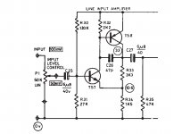
A general schematic like the one here

I have the feeling that a basic circuit well optimized, with the right layout and parts selection can give very high performance.
This "optimization" is not that easy process at all.
And on this basis i do not like very complex design because if it is difficult to optimized very basic circuits just think what kind of task is to optimized complex one.
I have always this KISS principle in my mind, even if i was looking at a very good preamp, the MBL 6010D and remained a little perplexed.
On the back there is written
In conclusion i would like to understand, before complicating the task, how much performance can i get from a two bjts buffer (i prefer bjts to fets).
My feeling is that a lot of performance can be got when all things are optimized.
First thing will be to try using some sim SW and see.
Thanks again and kind regards, gino
I am very interested in very good line driver/buffer designs because i really want to try a buffered volume control.
I have noticed that very decent power amps can be found quite easily.
Good line stages are much much less common
One of the main problem with SS is the 3D ability, while tubes are generally very good at this, but with other drawbacks that i do not like at all like soft bass and limited highs.
That buffer was intended to drive low ohmic headphones.
For lineamp only, you can use simpler buffer as this here in the beginning of this thread http://www.diyaudio.com/forums/solid-state/225255-jlh-buffer-homage-john-linsley-hood.html, or you can use something as Pass B1 buffer.
With symmetrical arrangement you can have no caps in the signal path.
Damir
Thanks a lot for your valuable advice.
I am not worried about caps in the signal path but i wonder how much performance can be obtained from an even simpler buffer gain stage, let's say with just a half of your really nice and elegant design, even if this of course will require the use of coupling caps.
A general schematic like the one here
I have the feeling that a basic circuit well optimized, with the right layout and parts selection can give very high performance.
This "optimization" is not that easy process at all.
And on this basis i do not like very complex design because if it is difficult to optimized very basic circuits just think what kind of task is to optimized complex one.
I have always this KISS principle in my mind, even if i was looking at a very good preamp, the MBL 6010D and remained a little perplexed.
On the back there is written
Then you open it and it is full of opampsHigh speed - single gain stage - design
In conclusion i would like to understand, before complicating the task, how much performance can i get from a two bjts buffer (i prefer bjts to fets).
My feeling is that a lot of performance can be got when all things are optimized.
First thing will be to try using some sim SW and see.
Thanks again and kind regards, gino
Last edited:
Dadod, do you try Hiraga 8w or 20w output stage ?
http://diyaudioprojects.com/Solid/Jean-Hiraga-Class-A-Amplifier/
http://diyaudioprojects.com/Solid/Jean-Hiraga-Le-Monstre/
http://diyaudioprojects.com/Solid/Jean-Hiraga-Class-A-Amplifier/
http://diyaudioprojects.com/Solid/Jean-Hiraga-Le-Monstre/
Last edited:
Hi and first sorry for the belated reply.
I am very interested in very good line driver/buffer designs because i really want to try a buffered volume control.
I have noticed that very decent power amps can be found quite easily.
Good line stages are much much less common
One of the main problem with SS is the 3D ability, while tubes are generally very good at this, but with other drawbacks that i do not like at all like soft bass and limited highs.
Thanks a lot for your valuable advice.
I am not worried about caps in the signal path but i wonder how much performance can be obtained from an even simpler buffer gain stage, let's say with just a half of your really nice and elegant design, even if this of course will require the use of coupling caps.
A general schematic like the one here
I have the feeling that a basic circuit well optimized, with the right layout and parts selection can give very high performance.
This "optimization" is not that easy process at all.
And on this basis i do not like very complex design because if it is difficult to optimized very basic circuits just think what kind of task is to optimized complex one.
I have always this KISS principle in my mind, even if i was looking at a very good preamp, the MBL 6010D and remained a little perplexed.
On the back there is written
Then you open it and it is full of opamps
In conclusion i would like to understand, before complicating the task, how much performance can i get from a two bjts buffer (i prefer bjts to fets).
My feeling is that a lot of performance can be got when all things are optimized.
First thing will be to try using some sim SW and see.
Thanks again and kind regards, gino
This is a so called "Schiklai", or CFP, arrangement. In order to make its performance as linear as possible, you need to load it with a constant current source (dynamic load), which will take another couple of transistors (at least)
Also, it is important to understand the input/output impedance requirements for the buffer - in many cases additional stage may be required just to satisfy those.
Yes, simulation will help...
This is a so called "Schiklai", or CFP, arrangement.
In order to make its performance as linear as possible, you need to load it with a constant current source (dynamic load), which will take another couple of transistors (at least)
Also, it is important to understand the input/output impedance requirements for the buffer - in many cases additional stage may be required just to satisfy those.
Yes, simulation will help...
Hi and thank you very much indeed for your valuable advice
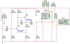
So you mean that a stage like the one attached has no chance to be linear and extremely low in distortion ?
This is a very fundamental question for me at this stage.
Anyway ... i understand that i am quite alone in seeing the challenge of achieving extremely good performance with extremely simple topologies
Maybe i am mistaking but i remember at least one very famous designer saying that after all his simpler (topology wise) designs were also the better sounding.
Personally i would start from that statement when selecting a suitable design, at least for a line stage that is the my major and almost only interest.
I wonder if someone is so nice to simulate it for me ... just for fun.
It could be a surprised.
The single supply voltage is 0-60V and the bjt can be almost all signal/driver pnps and npns. The pnp tends to heat up a little.
Kind regards, gino
Attachments
Last edited:
Dadod, do you try Hiraga 8w or 20w output stage ?
Jean Hiraga's Super Class-A Amplifier
Jean Hiraga's Le Monstre / Monster - DIY Class-A 8W Amplifier
No, I never tried any of those amps.
Hi and thank you very much indeed for your valuable advice
So you mean that a stage like the one attached has no chance to be linear and extremely low in distortion ?
This is a very fundamental question for me at this stage.
Anyway ... i understand that i am quite alone in seeing the challenge of achieving extremely good performance with extremely simple topologies
Maybe i am mistaking but i remember at least one very famous designer saying that after all his simpler (topology wise) designs were also the better sounding.
Personally i would start from that statement when selecting a suitable design, at least for a line stage that is the my major and almost only interest.
I wonder if someone is so nice to simulate it for me ... just for fun.
It could be a surprised.
The single supply voltage is 0-60V and the bjt can be almost all signal/driver pnps and npns. The pnp tends to heat up a little.
Kind regards, gino
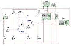
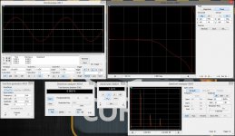
Simulation - easily
First picture shows the setup
With 36V power supply, collector current of Q1 = 330uA, Q2 = 5mA
Voltage gain = 10db
Frequency response - linear up to around 300KHz
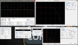
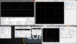
Second picture - output swing 1.12V RMS @ 1KHz
Third picture - same swing @ 20KHz
Forth picture - same as the third one, but showing the phase responce instead of the frequency one
Harmonics distribution is nice.
Lower power supply voltage leads to significant distortion increase.
If you have questions - let me know
Cheers,
Valery
Attachments
Simulation - easily
First picture shows the setup
With 36V power supply, collector current of Q1 = 330uA, Q2 = 5mA
Voltage gain = 10db
Frequency response - linear up to around 300KHz
Second picture - output swing 1.12V RMS @ 1KHz
Third picture - same swing @ 20KHz
Forth picture - same as the third one, but showing the phase responce instead of the frequency one
Harmonics distribution is nice.
Lower power supply voltage leads to significant distortion increase.
If you have questions - let me know
Cheers,
Valery
Valery, you are fast. When you are going to switch to LTspice as most members here are using it, and will be much easier to exchange .asc files between?
Dammir
Simulation - easily
First picture shows the setup
With 36V power supply, collector current of Q1 = 330uA, Q2 = 5mA
Voltage gain = 10db
Frequency response - linear up to around 300KHz
Second picture - output swing 1.12V RMS @ 1KHz
Third picture - same swing @ 20KHz
Forth picture - same as the third one, but showing the phase responce instead of the frequency one
Harmonics distribution is nice.
Lower power supply voltage leads to significant distortion increase.
If you have questions - let me know
Cheers,
Valery
Hi and first of all thank you very much indeed
I would not hope such amazing and very kind help
Yes ... i have a question ... how did you do that ?
My dream would be one day to be able to do the same myself
Please let me know what i have to do/buy
I am seriously interested and the results look fantastic !
Thanks a lot again
Kindest regards, gino
Gino, you can use LTspice software from Linear Technology, it's free download from their page, and you can find loot of help in this forum how to use that, but you have to have some electronic theoretical knowledge first.
Damir
Simulation - easily
First picture shows the setup
With 36V power supply,
If you have questions - let me know
Cheers,
Valery
Hi sorry Valery ... i have not been clear enough
The supply voltage is 60V not 36V !!!
This is the very secret ... a very high voltage supply i have been told.
maybe the distortion could be even lower ??? that would be fantastic !
If so i will focus completely on this circuit to try to build a line stage
I have already seen a kit on ebay for a nice 0-60V single power supply
Tell me about your set up to run this simulation ... i low the screen output.
Beautiful indeed !!!! Is it expensive ???
Thanks again and kind regards, gino
Last edited:
Gino, you can use LTspice software from Linear Technology, it's free download from their page, and you can find loot of help in this forum how to use that, but you have to have some electronic theoretical knowledge first.
Damir
Thanks a lot Damir ! but i fell in love with the screen outputs of Valery simulation software ... they look very very fine indeed
I wonder what is he using ? I guess is very expensive ?
Kind regards, gino
Oops ))
OK, sorry, no problem )
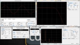
For 60V supply we have to use a higher voltage transistor than bc550.
See an updated schematic attached. Q2 will be good to equip with a small heatsink - dissipation will be around 200mW, relatively high for T)-92 transistor.
Overall distortion is a little bit lower, but what is more important - 3-rd harmonic (the "bad" one) is significantly lower. Don't worry about the 2-nd one. Very good performance for such a simple circuit.
Cheers,
Valery
Hi sorry Valery ... i have not been clear enough
The supply voltage is 60V not 36V !!!
This is the very secret ... a very high voltage supply i have been told.
maybe the distortion could be even lower ??? that would be fantastic !
If so i will focus completely on this circuit to try to build a line stage
I have already seen a kit on ebay for a nice 0-60V single power supply
Tell me about your set up to run this simulation ... i low the screen output.
Beautiful indeed !!!! Is it expensive ???
Thanks again and kind regards, gino
OK, sorry, no problem )
For 60V supply we have to use a higher voltage transistor than bc550.
See an updated schematic attached. Q2 will be good to equip with a small heatsink - dissipation will be around 200mW, relatively high for T)-92 transistor.
Overall distortion is a little bit lower, but what is more important - 3-rd harmonic (the "bad" one) is significantly lower. Don't worry about the 2-nd one. Very good performance for such a simple circuit.
Cheers,
Valery
Attachments
Last edited:
Thanks a lot Damir ! but i fell in love with the screen outputs of Valery simulation software ... they look very very fine indeed
I wonder what is he using ? I guess is very expensive ?
Kind regards, gino
This is Multisim 13.0 (National Instruments)
NI Multisim: Powerful Circuit Design and Teaching Software - National Instruments
Student edition is 25 euro
The one for designers is rather expensive
Last edited:
Valery, you are fast. When you are going to switch to LTspice as most members here are using it, and will be much easier to exchange .asc files between?
Dammir
Damir, I am moving slowly in this direction
Struggling with the user interface - commands, etc.
Multisim is much easier with regards to this... though, LTSpice is more precise, if used the right way...
OK, sorry, no problem )
For 60V supply we have to use a higher voltage transistor than bc550.
See an updated schematic attached. Q2 will be good to equip with a small heatsink - dissipation will be around 200mW, relatively high for T)-92 transistor.
Overall distortion is a little bit lower, but what is more important - 3-rd harmonic (the "bad" one) is significantly lower.
Don't worry about the 2-nd one.
Very good performance for such a simple circuit.
Cheers,
Valery
Valery, i cannot thank you enough
I can tell you that i tried to make a prototype of this circuit
I was the mind
a friend of mine the arm. I think he is quite good at diy, much much better than me. But he is a tube guy ... i think he is very wrong anyway ... tastes are tastes.We noticed that the pnp was heating up so we decided to use a toshiba pnp in to220 i do not remember the part, but it was a good one ... a 10W piece i think and this did not required the heatsink
Something like this one here ...
http://www.customworks.cz/wp-content/uploads/2012/09/2SA1837.pdf
( i would use even a 150W just to avoid the heatsink)
I was liking the sound quite ... nothing special i would say but decent
My friend was not impressed. We use cheap metal resistors but an attenuator and very good mundorf pp caps.
Then he replaced the feedback resistor with a Caddock i think ... or something similar.
What a big improvement. At that point the project stopped for his family problems (the prototype was in his living room and the wife protested)
even if i was sure that the circuit had some potential for good sound. I had this feeling.
To end i do not understand why so little effort is put on refining very basic circuits instead the designers prefer to go with complex topologies that i guess are even much more difficult to optimize.
I really do not understand this approach.
Thanks a lot again
Kind regards, gino
Last edited:
This is Multisim 13.0 (National Instruments)
NI Multisim: Powerful Circuit Design and Teaching Software - National Instruments
Student edition is 25 euro
The one for designers is rather expensive
Thanks a lot again Valery ! very very nice
I will buy the student edition immediately
Kind regards, gino
To end i do not understand why so little effort is put on refining very basic circuits instead the designers prefer to go with complex topologies that i guess are even much more difficult to optimize.
I really do not understand this approach.
Thanks a lot again
Kind regards, gino
I don't understand why some people think that using expensive components (caps, resistors, transformers) with very simple circuit and calling that optimizing, could get miracles sound out of it. The main distortion elements are semiconductors (or tubes) and improvement with better passives you can have only after the circuit is "optimized" with better configuration, semiconductors are much cheaper then exotic passives.
Everything should be made as simple as possible, but not simpler. ~Albert Einstein
Damir
I don't understand why some people think that using expensive components (caps, resistors, transformers) with very simple circuit and calling that optimizing, could get miracles sound out of it.
The main distortion elements are semiconductors (or tubes) and improvement with better passives you can have only after the circuit is "optimized" with better configuration, semiconductors are much cheaper then exotic passives.
Everything should be made as simple as possible, but not simpler. ~Albert Einstein
Damir
Hi and i am perfectly willing to agree with you. It was mainly the friend that is obsessed with these things.
I just like good parts but not exotic ones.
Good to know that active parts are the most critical.
I think that the simulations have answered most of my questions.
That is that acting of the various conditions like Vsupply, bias currents and so on very low distortion figures can be obtained with quite basic topologies.
I have to simulate something for myself now.
Thanks again for the helpful advice.
Kind regards, gino
- Status
- This old topic is closed. If you want to reopen this topic, contact a moderator using the "Report Post" button.
- Home
- Amplifiers
- Solid State
- Simple line buffer