I hope that Nelson has shown how to do this, BUT it is fairly easy with just a multimeter. You just short the gate to the source and add a 9V battery from the drain to the source. This gives you Idss. But how to measure? Put a 10 ohm resistor between the drain and the battery and measure across it. 0.1V=10ma and so forth. Matching Vbe is much more difficult.
Re: DMM
Can you recommend good JFETs in the 15-40mA range? How many would it take to find 4 that match at around 20mA? Is 10% considered an adequate match? And how much better would 2% matches be???
What I have in mind is matching 4 JFETs for the outputs to a headphone amplifier (for 300 ohm Sennheisers). I'm thinking about 2sk170, but don't know if I would need to buy 20, 50 or a 100 (to find enough that "match").
Sorry for a barrage of questions (I don't know if someone is reading that knows such things "like the back of their hand"). TIA.
JF
peufeu said:I then take a sheet of paper, mark a scale from (for instance) 15 to 40 mA, and drop the transistors...
Can you recommend good JFETs in the 15-40mA range? How many would it take to find 4 that match at around 20mA? Is 10% considered an adequate match? And how much better would 2% matches be???
What I have in mind is matching 4 JFETs for the outputs to a headphone amplifier (for 300 ohm Sennheisers). I'm thinking about 2sk170, but don't know if I would need to buy 20, 50 or a 100 (to find enough that "match").
Sorry for a barrage of questions (I don't know if someone is reading that knows such things "like the back of their hand"). TIA.
JF
Re: JFETs
: )
JF
peufeu said:I have only used JFETs to cascode bipolars so can't comment directly on their sound qualities.
I have used J309 in my DAC and that works well (and is cheap, too).
I think J309 would fit your bill, maybe. Look at the IDss values...
: )
JF
Hi,
Current sharing resistors not included? Or are they?
Cheers,")
you can put 4 in parallel to get that amount of current. Maybe with 3, but 4 to be certain.
Current sharing resistors not included? Or are they?
Cheers,
What comes closest to what I have in mind is Borbely's "Super Buffer" which is figure 8 at the following link:
http://www.borbelyaudio.com/borb502.pdf
I'm thinking of parallelling 4, 5, 6...or whatever of the jsk170/jsk74 to get 100mA. It seems that violet parts would help me get there at a lower part count (and are just a little more cost). Maybe you're suggesting 5 ohm series resistors to allow for differences between JFETs. Figure 9 shows a MOSFET version (with higher current output), but Borbely suggests that an all JFET amplifier would be the best.
My question is how closely matched (10, 5, 2%) do the k170/j74 pairs need to be?
JF
I hope that Nelson has shown how to do this, BUT it is fairly easy with just a multimeter. You just short the gate to the source and add a 9V battery from the drain to the source. This gives you Idss. But how to measure? Put a 10 ohm resistor between the drain and the battery and measure across it. 0.1V=10ma and so forth. Matching Vbe is much more difficult.
Following this guide looking at the datasheet for 2sk170bl - 0,00v over 10 Ohms... Tried 4 of them now. Maybe the battery is old. Even moved everything down my experiment board - no dice...
Regards
Following this guide looking at the datasheet for 2sk170bl - 0,00v over 10 Ohms... Tried 4 of them now. Maybe the battery is old. Even moved everything down my experiment board - no dice...
Regards
Battery broken...
Regards
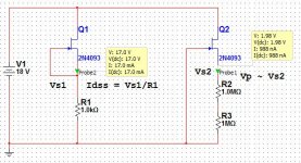
The Nelson Pass page with explanations and diagrams is "Matching Devices" at https://www.passdiy.com/project/articles/matching-devicesI hope that Nelson has shown how to do this, BUT it is fairly easy with just a multimeter. You just short the gate to the source and add a 9V battery from the drain to the source. This gives you Idss. But how to measure? Put a 10 ohm resistor between the drain and the battery and measure across it. 0.1V=10ma and so forth. Matching Vbe is much more difficult.
My atch diagram is taken from a circuit simulator (Multisim) but illustrates the concepts.
Dale
Attachments
You can pretty much measure everything with a DMM and a sound card :
FET Measurements with Just A DMM
Patrick
FET Measurements with Just A DMM
Patrick
- Status
- This old topic is closed. If you want to reopen this topic, contact a moderator using the "Report Post" button.
- Home
- Amplifiers
- Solid State
- Matching Jfets