More than that broken.
sometimes it is good to own a server ...
OT: discrete opamp
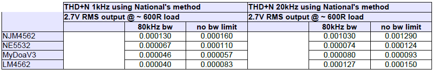
Using National's measurement method we get following amazing results. See attached table.
Analyzer input and output level 2.7Vrms.
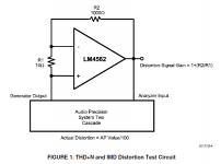
R1=18R, R2=1800R, load ~ 600R
IMHO MyDOA-V3 looks here very good.")
NE5532 also better as expected and has even better 20kHz THD+N figure as LM4562 (couldn't believe this so I tried a second LM4562 sample).
DC offset is one of the things which commercial opamps do here better as MyDOA-V3. Today I have designed a dc adjustable version of MyDOA-V3. Need some time to get the new pcb. Stay tuned...
Br, Toni
Using National's measurement method we get following amazing results. See attached table.
Analyzer input and output level 2.7Vrms.
R1=18R, R2=1800R, load ~ 600R
IMHO MyDOA-V3 looks here very good.
NE5532 also better as expected and has even better 20kHz THD+N figure as LM4562 (couldn't believe this so I tried a second LM4562 sample).
DC offset is one of the things which commercial opamps do here better as MyDOA-V3. Today I have designed a dc adjustable version of MyDOA-V3. Need some time to get the new pcb. Stay tuned...
Br, Toni
Attachments
Last edited:
Hi Tony,
Great results!
1) Who's NE5532 are you using? I recall Doug Self writing that the TI's were the worst of the bunch, that Onsemi/Fairchild/JRC measured better.
2) Where are you getting pcb's made?
3) I guess you would get better offset with a monolythic dual, but difficult to get in THT these days. Old LM394 gone away. No need for extra complexity/size to use a servo.
4) Do you own AP equipment? What are you using to measure these results?
Thanks
Rick
Hi Tony,
Great results!
1) Who's NE5532 are you using? I recall Doug Self writing that the TI's were the worst of the bunch, that Onsemi/Fairchild/JRC measured better.
2) Where are you getting pcb's made?
3) I guess you would get better offset with a monolythic dual, but difficult to get in THT these days. Old LM394 gone away. No need for extra complexity/size to use a servo.
4) Do you own AP equipment? What are you using to measure these results?
Thanks
Rick
Dear rick,
Ad 1) NE5532AN, NE5534AN from onsemi
Ad 2) Leiterplatten online kalkulieren & bestellen - LeitOn
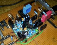
Ad 3) You are right. A simple multi turn pot seems to be enough to get good dc values and keep low distortion (as seen on the lab test picture)
Ad 4) I have bought a used VP7723D from Levear/Panasonic which is able to measure down to something like 0.0003% at 1kHz (datasheet facts: better as 0.001% 20Hz to 15kHz/ 80kHz bandwidth). More as enough for hobby electronics.
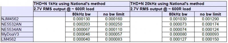
Attached the corrected THD+N table. I have measured erroneously a NE5534AN instead of a NE5532AN. NE5534AN performs here better as a NE5532AN
Br, Toni
Attachments
Last edited:
Wonderful work. I always wondered how well a 5532 compared with 5534.
I am surprised with the LM4562 20K #'s.
Still goes to show that the 5534 was a fantastic part for the time frame that it was developed. So the MyDOA-V3 is in the leagues with the finest of designs, cheers to you.
I built a pre-amp as a college project that used the 5533 ( a Signetics 5534 dual). I was impressed at how it sounded comparing against my Pioneer SX-950 pre-amp/phono sections.
Rick
Toni, what gain are these THD measurements?Attached the corrected THD+N table. I have measured erroneously a NE5534AN instead of a NE5532AN. NE5534AN performs here better as a NE5532AN
As for the latest noise measurements, all I can say is that the 20kHz SC noise numbers are close(r?) to what I expect and all the OPAs are very quiet.
Still dunno what the Levear is doing on its special noise mode.
Wonderful work. I always wondered how well a 5532 compared with 5534.
I am surprised with the LM4562 20K #'s.
Still goes to show that the 5534 was a fantastic part for the time frame that it was developed. So the MyDOA-V3 is in the leagues with the finest of designs, cheers to you.
I built a pre-amp as a college project that used the 5533 ( a Signetics 5534 dual). I was impressed at how it sounded comparing against my Pioneer SX-950 pre-amp/phono sections.
Rick
Dear Rick,
thanks! I will give my best! PM me if you want some pcb samples ...
IMHO regarding NE5532 and NE5534 Douglas Self is completely right. After such many time of opamp testing, hearing and measurement I personally would say these old devices are still usable in high end audio applications.
BR, Toni
Toni, what gain are these THD measurements?
See schematic from post # 782. I have used 1800R and 18R instead - same gain of 101 but output signal is same voltage as input signal ~ should simulate unity gain with 100 times distortion signal...
First it measures the input/output level at given frequency and afterwards it switches off signal generator to measure the silence voltage.As for the latest noise measurements, all I can say is that the 20kHz SC noise numbers are close(r?) to what I expect and all the OPAs are very quiet.
Still dunno what the Levear is doing on its special noise mode.
BR, Toni
OT: discrete opamp
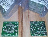
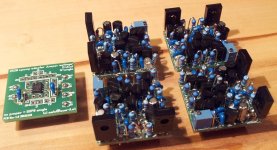
sorry for such a long time without any update. November and december we have had very much to do at work so I haven't had any spare time to continue with the projects. Today I have had time to assemble and solder my first 4 pieces of MyDOA v3.1
I have used only parts from stock. No testing done be4. No matching done. Just directly assembled and soldered. Powering up, adjusting DC offset, ready.
Working out of the box without any problems!
Quick THD measurements showed only very small deviation of THD20k. Also square wave results are very good.
The attached picture shows a self designed adapter pcb so I can quickly compare MyDOA v3.1 with different industrial devices.
Now I have enough parts to start hearing tests with my friends...
Merry christmas!
Toni
Attachments
Kudos to you, truly amazing measurement results, Toni!! I am very curios to listen to your OP- amp`s!
Cheers, Martin
Thx!
This is an invitation to you: maybe you have time these days to participate at our listening tests with and without ethyl ...
BR, Toni
OT: SA2012 / LME49830/IRFP240/IRFP9240
For those people who want to know what means "astx 4-channel beast" have a look at Project | Homebuilt Hi-Fi - A user submitted image showcase of high quality home built hi-fi components.
Martin has built my SA2012 (LME49830/IRFP240/IRFP9240 based 4 channel amplifier).
His skills on metal work are outstanding!
If you compare this with my "cheap" designed SA2012 prototype you know what I mean! Attached a picture of SA2012 prototype.
Br, Toni
YESSS, of course! I bring the astx 4-channel beast for you to have a close look on the finished unit. Plus I would love to have it tested and measued by it´s designer in person
See you soon, Martin
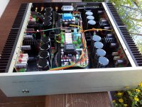
For those people who want to know what means "astx 4-channel beast" have a look at Project | Homebuilt Hi-Fi - A user submitted image showcase of high quality home built hi-fi components.
Martin has built my SA2012 (LME49830/IRFP240/IRFP9240 based 4 channel amplifier).
His skills on metal work are outstanding!
If you compare this with my "cheap" designed SA2012 prototype you know what I mean! Attached a picture of SA2012 prototype.
Br, Toni
Attachments
Update: VAS current protection redesign
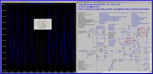
As discussed in dadod's (=damir) 200w-mosfet-cfa-amp most VAS current protections are either missing or misconfigured. Here is the revised schematic for the Input/VAS stage of my SA2013 Amplifier.
R2 has been added to protect Q6 during amplifier overload.
To improve the GM/PM after adding this resistor, C35 has been added.
These changes are only simulation results and therefore needs real life testing. After successful tests the updated pcb will follow.
BR, Toni
Attachments
My suggestions:
1. Put about 10V zener diode between Q6 collector and V+VAS. Adjust R2 if neccessary. This will short collector AC voltage , which may othervise go to VAS input through Q6 Cbc.
2. And then connect Q37 collector to Q6 collector instead base, then adjust R22a if necessary. Usually Q37 start conduct at about 1/4 limiting value, so You must set limiting value very high, or risk some distortions.
Toni have you experimented with baker style diode over vas. And seen how it affects current in vas emitter follower driver transistor during clipping and overload.
Regards.
Dear vostro,
thx for your idea.
Unfortunately a diode from VAS output to base of Q6 worsens distortion extremely. Think this has been discussed in this thread some time ago...
A diode in this place adds a voltage dependent miller capacitance which destroys the optimized TMC values and hence add distortions.
An example: THD20k@200W@8R increases dramatically from 0.000476% to 0.014619% using ltspice diode type ES1D (we need here a diode with > 150V breakdown).
You are right: using a diode avoids saturation of Q6 and hence the Q6-overload during clipping.
So one can decide:
- some sticking at overload but lowest distortion during normal mode:
add R2 to protect SOA of Q6. Avoid diode. - best amplifier overload behaviour but increased distortions during normal running mode: add diode, remove R2
Br, Toni
- Home
- Amplifiers
- Solid State
- 2stageEF high performance class AB power amp / 200W8R / 400W4R