Hey Guru Zan,
You did read Cherry's papers on NDFL, didn't you?
The point is that I'm puzzled by one thing. In his JAES article, May 1982, p. 302, he introduces some magic factor sqrt3 -1 (see pic), which should make the response "phase linear". If I use this magic factor (in stead of making the time constants just equal) I get overshoot. Now I've three questions:
1. Where did this magic factor come from? (btw, I have seen it elsewhere, but forgot where and in what context).
2. Is it possible to make a circuit phase linear and still get overshoot?
3. Or has Cherry just made a mistake?
I would be grateful if you could shed some light on these questions.
Cheers, E.
I hope you will accept answers from non-Gurus
1a. Calculate H(jw), then calculate d(PH(H(jw))/dw = const. and get a relation between Tf and Tx. The parametric Tf=Tx is called the trivial solution, since it makes the two poles overlap (doesn't make sense in the NDFL context). You need about three pages of algebra.
1b. Use a signal processing theory result, saying that a system is phase linear if H(s)=s^(-N)*H(1/s) where N is the system order (N=2 here). This is derived from a theorem stating that linear phase systems have always symmetric impulse responses. Another three pages of algebra to get the relationships between Tx and Tf.
2. Not for minimum phase systems (without a relevant RHP zero). In general it's possible, for example some filter types, having otherwise non linear phase, can be optimized for linear phase in the pass band, at the expense of the constant amplitude response.
3. No mistake.
The rt(3) factor comes from a 2nd order Bessel filter eg Table 1 row 4 of RaneNote147 A Bessel Filter Crossover, and Its Relation to OtherslIn his JAES article, May 1982, p. 302, he introduces some magic factor sqrt3 -1 (see pic), which should make the response "phase linear".
A Bessel is Linear Phase only within the passband. Above the LP cutoff, phase is wonky.If I use this magic factor (in stead of making the time constants just equal) I get overshoot.
If you filter your square wave with a Linear Phase brickwall filter, you will see Gibb's ringing and other stuff. If you now filter this with a Bessell LP at a slightly lower frequency, the ringing miraculously goes away cos there are no components outside the passband. Everything is delayed by the 'linear phase' part of the filter.
Dis pseudo guru apologises for misleading da unwashed masses & yus true gurus alike.kgrlee said:The limiting case for no time domain overshoot is a Bessel filter. The Q=0.5 2nd order system is the simplest Bessel.
The simplest Bessel (2nd order) is Q=1/rt(3)=0.5774. As Guru Stuart points out, this still overshoots if your input has bits outside the passband.
The condition for no overshoot in 2nd order systems is Q<0.5 The mechanicals call this Critical Damping
My excuse is I kunt reed en rite. Mea maxima culpa

Dis bit and the other parts of my post are accurate.But Q=0.7 is where the 'distance from (-1,0)' shows no peaking. This is a 2nd order Butterworth filter which does overshoot in time.
The EXACT correlation between 'distance from (-1,0)' and Overshoot depends on the order of the system.
But the Peaking in Amplitude Response is given EXACTLY[*] by the Feedback Eqn which just looks at the magnitude of the Denominator .. which is the distance from (-1,0) regardless of order.
Hi Richard,
Thanks for explanation.
As for overshoot, if the effect of the input filter (defined by 1kOhm & 680pF) and output filter (defined by 6.8uH & 8Ohm) is also taken into account, then the overshoot has (almost completely) vanished. Nevertheless I prefer to set Tf equal to Tx and use critically damped I/O filters.
Cheers, E.
NDFL
Hi Richard,
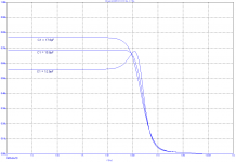
Agreed, for a maximally flat group delay Q should be1/rt(3), thus Tf = ( rt(3) -1 ) * Tx or C1 = 12.9pF. With this value I got some overshoot. Okay. That's also what I found in the textbooks. But I'm still not satisfied.
First, the overshoot is much larger (10x) than reported by Cherry (0.5%).
Second, a simulation of the group delay is far from flat (see pic).
For maximum flatness I had to increase C1 to 15.8pF and for critical damping (Q=0.5) to17.6pF.
Because of above discrepancies I'm not sure whether Cherry's NDFL circuit is just a ordinary 2nd order (Bessel) system. Besides, also the onset of the step response looks different (more like a 1st order LPF). Could it be that Cherry's analysis is a little oversimplified?
Cheers, E.
Hi Richard,
Agreed, for a maximally flat group delay Q should be1/rt(3), thus Tf = ( rt(3) -1 ) * Tx or C1 = 12.9pF. With this value I got some overshoot. Okay. That's also what I found in the textbooks. But I'm still not satisfied.
First, the overshoot is much larger (10x) than reported by Cherry (0.5%).
Second, a simulation of the group delay is far from flat (see pic).
For maximum flatness I had to increase C1 to 15.8pF and for critical damping (Q=0.5) to17.6pF.
Because of above discrepancies I'm not sure whether Cherry's NDFL circuit is just a ordinary 2nd order (Bessel) system. Besides, also the onset of the step response looks different (more like a 1st order LPF). Could it be that Cherry's analysis is a little oversimplified?
Cheers, E.
Attachments
As you've confirmed, the condition for no overshoot is Q=0.5Agreed, for a maximally flat group delay Q should be1/rt(3), thus Tf = ( rt(3) -1 ) * Tx or C1 = 12.9pF. With this value I got some overshoot. Okay. That's also what I found in the textbooks. But I'm still not satisfied.
First, the overshoot is much larger (10x) than reported by Cherry (0.5%).
Second, a simulation of the group delay is far from flat (see pic).
For maximum flatness I had to increase C1 to 15.8pF and for critical damping (Q=0.5) to17.6pF.
Because of above discrepancies I'm not sure whether Cherry's NDFL circuit is just a ordinary 2nd order (Bessel) system. Besides, also the onset of the step response looks different (more like a 1st order LPF). Could it be that Cherry's analysis is a little oversimplified?
The Bessel WILL show some overshoot on an unlimited bandwidth input. I'm not sure which Cherry amp you are simulating but they will all have some input filtering which will reduce the overshoot.
Whether you choose
- Q=0.5 Critical Damping
- Q=0.5774 Bessel
- Q=0.7 Butterworth : No peaking. Probably my choice
But there is another consideration. Once you start nesting loops, the system is no longer 2nd order but only approximates it at LF and becomes seriously wonky at HF.
As I said earlier, for higher order systems, the relationship between the amplitude response measures like Q [*] and time response overshoot become more complicated.
[*]Q is a direct measure of peaking at the 'resonant' frequency of a 2nd order system. eg Q=1/rt(2) gives -3db response, Q=2 gives 6dB peak etc
Hi Richard,
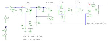
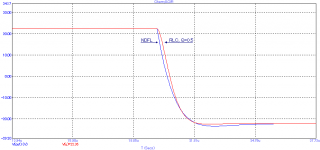
The simulating is based on the circuit from JAES, Vol. 30, No.5, 1982 May, p. 303. The semiconductors however, are replaced by ideal components like a VCCS, CCCS and VCVS, see below. The 2nd picture shows the step response of the NDFL amp (blue curve) as well as of a simple 2nd order critically damped LPF (red curve).
Cheers, E.
errata previous post: That's mostly the case here. should read: That's most likely the case here.
Attachments
Last edited:
The rt(3) factor comes from a 2nd order Bessel filter eg Table 1 row 4 of RaneNote147 A Bessel Filter Crossover, and Its Relation to Othersl
[...]
Postscriptum
Finally, after all those years, this magic factor makes sense to me. All the time I've overlooked that Cherry not only included the R-C Zobel part in his analysis, but also the L-RL part. I should have read his paper more carefully.

On the other hand, I still consider it a little weird to include the L-RL part, because RL (the speaker impedance) is an unknown factor. Therefore I prefer to exclude the entire Zobel network from the analysis and treat it as a separate entity.
Anyhow, if we look at the signal after the Zobel network (see pic), and assume that RL is indeed 8.2 Ohms, then we are dealing with a 2nd order system and this magic factor makes sense and C2 should be 12.9pF for a maximally flat GD.
Cheers, E.
Attachments

Well spotted Edmond.On the other hand, I still consider it a little weird to include the L-RL part, because RL (the speaker impedance) is an unknown factor. Therefore I prefer to exclude the entire Zobel network from the analysis and treat it as a separate entity.
Anyhow, if we look at the signal after the Zobel network (see pic), and assume that RL is indeed 8.2 Ohms, then we are dealing with a 2nd order system and this magic factor makes sense and C2 should be 12.9pF for a maximally flat GD.
Cherry isn't the only competent amp designer that has rather naive ideas about the loads speakers present.
In my role as an evil speaker designer
, I had a similar conversation with Peter Walker & Mike Albinson of QUAD about the protection on the original 405. I like to think this had something to do with the less restrictive protection on the 405.2 and later versions.Then there are the incompetents like Otala who falsely accuse speakers of even more Unobtainium evils.
Last edited:
Has anyone LTSPICE compared TMC vs. MC compensation when there is a 5uF - 20uF capacitor load added in parallel with an 8-ohm speaker load?
My simulations show MC to have superior tolerance to parallel capacitor+speaker loads, especially with symmetrical input topologies, and especially at high frequencies.
Robust design vs. lowest THD?
My simulations show MC to have superior tolerance to parallel capacitor+speaker loads, especially with symmetrical input topologies, and especially at high frequencies.
Robust design vs. lowest THD?
Has anyone LTSPICE compared TMC vs. MC compensation when there is a 5uF - 20uF capacitor load added in parallel with an 8-ohm speaker load?...
I have not compared that specific load because it does not resemble any of my speakers.
But "two pole" schemes like TPC and TMC (actually at least two pole and at least one zero) can do better on distortion at the same level of stability, or more stability for the same distortion, compared to simple one pole schemes.
If your simulations don't show this then they are probably not optimized, not always obvious.
Post them if you want them checked.
There are always trade-offs within a particular scheme of course.
Best wishes
David
Last edited:
uF load on audio power amplifier output doesn't look like any known speaker load - why would you think of it?
ES loudspeaker with step up transformer have winding leakage L and series R in between the reflected panel C and the amplifier output - essentially makes a pretty good decoupling network for stability purposes
amps for ES loudspeakers do have to have beefy output stages for the unusual phase angle, potentially high current
With my evil speaker designer hat on ...Has anyone LTSPICE compared TMC vs. MC compensation when there is a 5uF - 20uF capacitor load added in parallel with an 8-ohm speaker load?
There are no speakers, electrostatic or otherwise, that even approximate this load. If anyone has knows different, please post the evidence.
However, in a well designed amplifier, this is NEVER the most serious load for instability.
uF load on audio power amplifier output doesn't look like any known speaker load - why would you think of it?
In audio magazine reviews, Krell claimed their KRS amps are "stable with a 10uF capacitive load" and "can drive 1 ohm speakers". I use these stability tests in my LTSpiceSims. I have seen other amps spec 1uF stability.
My experience:
My VFA amp design with MC compensation produces a clean and stable 200W LTSpice simulation with an 8-ohm complex RLC speaker load PLUS a 10uF capacitor in parallel. This design can pass this 10uF LTSpiceSim even without the normal output LC series filter. Also drives a 1ohm speaker load up to the power supply limits.
The same VFA amp design with TMC compensation has 2-3x lower LTSpiceSim THD than with MC, but cannot pass LTSpiceSims with an 8-ohm complex RLC speaker load PLUS a 1uF capacitor in parallel. Same failure with the DC servo removed.
My CFA amp design with the same TMC compensation components will LTSpiceSim with a parallel 10uF capacitor load, but only with very high THD.
Next time you are running a TMC amplifier simulation .... why not .... add a 1uF or 5uF capacitor load test. Be prepared for UTube
Why don't you post the LTspice *.ASC files and your models so we can see how you've achieved these astounding results with evil but totally unrepresentative loadsMy VFA amp design with MC compensation produces a clean and stable 200W LTSpice simulation with an 8-ohm complex RLC speaker load PLUS a 10uF capacitor in parallel. This design can pass this 10uF LTSpiceSim even without the normal output LC series filter. Also drives a 1ohm speaker load up to the power supply limits.
The same VFA amp design with TMC compensation has 2-3x lower LTSpiceSim THD than with MC, but cannot pass LTSpiceSims with an 8-ohm complex RLC speaker load PLUS a 1uF capacitor in parallel. Same failure with the DC servo removed.
My CFA amp design with the same TMC compensation components will LTSpiceSim with a parallel 10uF capacitor load, but only with very high THD.
What happens when your amps 'fail'?
Hi Ric
This is a few ideas in response to your questions in Toni's and Damir's threads, continued here so as not to threadjack.
I now understand the feedforward, inner/outer loop issue much better, at last
As usual, the information was already in Bode and Middlebrook and I just didn't realize the implications previously.
First point is that you have always claimed the Output Inclusive Compensation ("Cherry") was special, I now see that there is an aspect for which this is true.
Cherry has practically no direct transmission so it behaves practically exactly as simple one loop theory would predict.
So called "simple" Miller compensation turns out to have sufficient direct transmission to make one loop, idealized unilateral transmission quite inaccurate.
It is precisely this fact that makes it important to consider and compensate both the inner and outer loop.
It also makes possible the unstable inner + stable outer loop that has been mooted.
While it may not show in the outer loop stability plot, it would normally show in the closed loop response.
But even that is not mathematically inevitable AFAIK.
So Cherry is special in that it's closeness to ideality will remove these complications.
Hurst points out that is not just the ratio of direct transmission to reverse transmission that is important.
The impedances at the input and output matter too.
Cherry seems to illustrate this, even with the same compensation capacitor as Miller compensation, they are very different in how close to ideal they are.
Second point is on the interpretation and importance of the Non Minimum Phase behaviour.
NMP can occur in arbitrary paths in the amplifier, for instance one of the paths into the star node of TMC, due to other parallel paths.
I don't think this matters.
NMP in the Return Ratio of an active device does matter and is practically always undesirable.
So the discussion of NMP has been confused by a failure to separate these two cases.
At least that's what I think now and it seems obvious in retrospect
Does this make sense?
Best wishes
David
Last edited:
For those who just jumped into this, Guru Zan's post is the latest product of a long line of investigation which started (for me) about post #659 of http://www.diyaudio.com/forums/solid-state/243481-200w-mosfet-cfa-amp-66.html going onto page 74.
It investigates Minimum & Non-Minimum Phase (NMP) behaviour and other things which affect stability and also how we look & judge it.
There are many important contributions from major & minor gurus including Harry Dymond, Damir & Toni who contributed a nifty Table method of Parameter Stepping with multiple Tian probes at post #1226 of his 2stageef-high-performance-class-ab-power-amp-200w8r-400w4r
My $0.02 is at #1242 and #1250 though they are useful nuggets of wisdom from the other gurus until page 125 of Toni's thread.
_______________________
What I was trying to show in my post #1250 on Toni's thread was that it is possible to make the amp NMP by increasing the global feedback in Toni's Table example with simple Miller compensation. Damir seems to be able to make his amp switch between MP & NMP behaviour too but his example has 2 obvious paths.
I've just tried to make one of my 'pure Cherry' examples do this without success. Converting it to plain Miller allows this pseudo evil behaviour.
I stress in #1251 that this behaviour appears innocuous as there is no sudden change in the 'outer loop' or closed loop behaviour when the 'inner loop' swaps from MP to NMP behaviour.
I think we need to distinguish between this type of NMP behaviour (totally absent with the Holy 'pure Cherry' )
and
the NMP behaviour due to RHP poles at or above ULGF which are absolutely evil. Is this your NMP in the Return Ratio of an active device ?
___________________________
Thanks also for Hurst Compare2FbApproaches
After a bottle or two of Nurofen, I've finally twigged that the way I calculated 'Loop Gain' (with zillion H inductors etc) in Jurassic times, is in fact more akin to Hurst's (& I presume Bode's) Return Ratio.
What I didn't take into account is 'direct signal feedthrough', his d in Eqn (1) and I can only pre10 to unnerstan dis S pac.
___________________________
Thanks to you and the other gurus (especially Damir & Toni for bearing with us hijackers) for the new insights.
They enable me to explain stuff which I've seen while playing with the sims for this thread and also lead to small changes which have quite big effects on overall (especially overload) performance.
More to come.
It investigates Minimum & Non-Minimum Phase (NMP) behaviour and other things which affect stability and also how we look & judge it.
There are many important contributions from major & minor gurus including Harry Dymond, Damir & Toni who contributed a nifty Table method of Parameter Stepping with multiple Tian probes at post #1226 of his 2stageef-high-performance-class-ab-power-amp-200w8r-400w4r
My $0.02 is at #1242 and #1250 though they are useful nuggets of wisdom from the other gurus until page 125 of Toni's thread.
_______________________
Guru Zan, thank you for showing 'pure Cherry' is compensation as God intended.First point is that you have always claimed the Output Inclusive Compensation ("Cherry") was special, I now see that there is an aspect for which this is true.
Cherry has practically no direct transmission so it behaves practically exactly as simple one loop theory would predict.
What I was trying to show in my post #1250 on Toni's thread was that it is possible to make the amp NMP by increasing the global feedback in Toni's Table example with simple Miller compensation. Damir seems to be able to make his amp switch between MP & NMP behaviour too but his example has 2 obvious paths.
I've just tried to make one of my 'pure Cherry' examples do this without success. Converting it to plain Miller allows this pseudo evil behaviour.
I stress in #1251 that this behaviour appears innocuous as there is no sudden change in the 'outer loop' or closed loop behaviour when the 'inner loop' swaps from MP to NMP behaviour.
I think we need to distinguish between this type of NMP behaviour (totally absent with the Holy 'pure Cherry'
) and
the NMP behaviour due to RHP poles at or above ULGF which are absolutely evil. Is this your NMP in the Return Ratio of an active device ?
___________________________
Thanks also for Hurst Compare2FbApproaches
After a bottle or two of Nurofen, I've finally twigged that the way I calculated 'Loop Gain' (with zillion H inductors etc) in Jurassic times, is in fact more akin to Hurst's (& I presume Bode's) Return Ratio.
What I didn't take into account is 'direct signal feedthrough', his d in Eqn (1) and I can only pre10 to unnerstan dis S pac.
___________________________
Thanks to you and the other gurus (especially Damir & Toni for bearing with us hijackers) for the new insights.
They enable me to explain stuff which I've seen while playing with the sims for this thread and also lead to small changes which have quite big effects on overall (especially overload) performance.
More to come.
Last edited:
- Status
- This old topic is closed. If you want to reopen this topic, contact a moderator using the "Report Post" button.
- Home
- Amplifiers
- Solid State
- TPC vs TMC vs 'pure Cherry'