On the method of simulating the inner loop gain, I've seen others disable the global loop with a massive inductance in series with the global feedback resistor.
<nitpick>
That would provide a sufficient condition for stability. That is, it is possible to have an unstable inner loop, and the amplifier to be globally stable.
The most direct method of assessing stability of multi loop systems is to compute the eigen values of the closed loop system matrix. Other than in very simple cases, this is not practical in audio circuits because the poles are often widely separated and the order of the system can also be quite high.
Probably the easiest method in the frequency domain is the procedure called "sequential loop closures", or "sequential return differences":
1. Open all loops such that the resulting system is stable.
2. Assess the loop gain of one loop with all other loops open. Keep track of the number of clockwise encirclements of the Nyquist point.
3. Close that loop and assess the loop gain of the next loop. Keep track of the net number of encirclements of the Nyquist point.
4. Close that loop and do the same for the next loop.
5. Repeat for all loops.
At the end, if the net number of encirclements (clockwise - counter clockwise) equals zero, the system is stable. If the net number is greater than zero, the system is unstable.
This procedure is mathematically exact, however it has one practical shortcoming: it is hard to identify a single phase margin and/or gain margin. You could take the minimum phase margin and minimum gain margin as assessed for each loop, but then you may get different numbers if you select a different evaluation sequence.
Note that assessing one loop while other loop(s) are closed is rigorously wrong. It leads to a case of circular logic: when analyzing loop A, you don't know if loop B (closed) has a RHP. If it would, then loop A has to encircle the Nyquist point exactly once (counter clockwise) to make the overall system stable. That would be equivalent to say that loop A is stable because loop B is stable, and loop B is stable because loop A is stable.
</nitpick>
Mike, your two-transistor VAS/TIS and triple output is outside what kgrlee is proposing (and what Cherry analysed)
This shouldn't affect the outcome.
Also, you don't have the VAS/TIS emitter resistor and kgrlee's parallel capacitor. Does addressing these issues change the outcome?
No.
Potentially the bootstrap VAS/TIS load and the load stabilising network should be added also (post #41), though I don't know whether these have any significant influence.
A bootstrap load and a Thiel network shouldn't change the outcome. Note that in my simulation the amplifiers are unloaded.
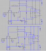
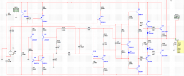
On the method of simulating the inner loop gain, I've seen others disable the global loop with a massive inductance in series with the global feedback resistor. Is that what you have also? In the bottom schematic, the feedback component looks like an inductor, but in the top circuit it looks like a resistor. Maybe just the grid points blurring the picture.
No, I did not disable the major feedback loop because it is important to examine the stability of the minor loop in the presence of the major loop.
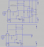
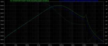
But I have repeated the simulation with the major loop disabled by means of a large capacitor (1K) across the inverting input of the amplifiers.
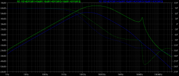
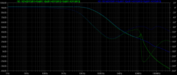
As you can see the minor loop is still unstable without shunt capacitance on the second stage output.
The blue trace denotes minor loop gain with shunt capacitance at the output of the second stage. Phase shift at unity minor loop gain is 135 degrees at 9MHz, while without shunt compensation of the loop (green trace) you have phase shift of 197 degrees at 44MHz.
Attachments
To summarise, never use raw output inclusive compensation because you would have to include at least 1nF shunt capacitance across the second stage to make the minor loop stable; you would probably need a good deal more shunt capacitance if you intend to use a BJT output stage. This shunt capacitance is not ideal as it provokes distortion in the second stage.
If you have to use output inclusive compensation, then use "TMC" instead, but note that you mustn't use lead compensation with it because this adds an undesirable zero to the loop enclosing the output stage which drastically increases that loop's unity gain frequency; this, together with the output stage poles, provokes instability.
However, from my investigations, there's no need to use output inclusive compensation at all; just use TPC, or TPC with MIC. The only reservation I have with MIC is that the unity minor loop gain frequency of the MIC loop exceeds 45MHz even when compensated, so to be on the safe side just use ordinary TPC.
Last edited:
OPS Compensation
The side effect of the 1 nF shunt CAP is reducing slew rate dramatically.
However, there is another way to make every thing stable without that shunt CAP.
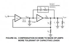
I find this paper which may give us a hint. Please see figure 3A in this paper.
http://www.intersil.com/content/dam/Intersil/documents/an10/an1092.pdf
The key is to make output pole more dominant.
I suggest the Gm of the VAS should not be greater than 1/RC in Figure 3A. Degenerating VAS should be required.
To summarise, never use raw output inclusive compensation because you would have to include at least 1nF shunt capacitance across the second stage to make the minor loop stable
The side effect of the 1 nF shunt CAP is reducing slew rate dramatically.
However, there is another way to make every thing stable without that shunt CAP.
I find this paper which may give us a hint. Please see figure 3A in this paper.
http://www.intersil.com/content/dam/Intersil/documents/an10/an1092.pdf
The key is to make output pole more dominant.
I suggest the Gm of the VAS should not be greater than 1/RC in Figure 3A. Degenerating VAS should be required.
Attachments
Last edited:
The side effect of the 1 nF shunt CAP is reducing slew rate dramatically.
However, there is another way to make every thing stable without that shunt CAP.
I find this paper which may give us a hint. Please see figure 3A in this paper.
http://www.intersil.com/content/dam/Intersil/documents/an10/an1092.pdf
The key is to make output pole more dominant.
I suggest the Gm of the VAS should not be greater than 1/RC in Figure 3A. Degenerating VAS should be required.
Yes, the shunt capacitance on the second stage may become the slew rate limiting factor.
I fail to appreciate how making the output stage pole "more dominant" would stabilise the minor loop in an OIC amplifier. On the contrary, intuition suggests it would make matters worse.
Yes, the shunt capacitance on the second stage may become the slew rate limiting factor.
I fail to appreciate how making the output stage pole "more dominant" would stabilise the minor loop in an OIC amplifier. On the contrary, intuition suggests it would make matters worse.
The problem for OIC is to make VAS+OPS stable at Unit Gain.
In order to make things simple, I put input stage aside.
In normal case, the pole in OPS is not low enough. The system still has lots of gain when phase shift exceed 180 degree. The key is to make the pole more dominant. In another words, make the pole lower. Thus, the gain rolls off more earlier.
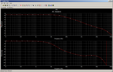
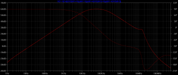
I simulated open loop gain for VAS + OPS (with out INPUT STAGE). I used the technique I mentioned http://www.diyaudio.com/forums/solid-state/235188-tpc-vs-tmc-vs-pure-cherry-7.html#post3479756 to compensate output stage. (See R12 C1) From this chart, VAS + OPS will be stable at Unit Gain. It is not question that OIC will definitely stable as well.
PS: The chart will be different if you remove 8 Ohm load. I am not sure about if that may cause issue.
Attachments
Last edited:
The key is to make the pole more dominant. In another words, make the pole lower. Thus, the gain rolls off more earlier.
What you clearly haven't understood is that with the loading of the miller compensation capacitor moved from the second stage to the output, the second stage continues to generate gain long after the output stage poles take effect. This is what causes a multi-pole roll off within the OIC loop, and, therefore, causes instability within that loop.
Now, lowering the dominant output stage pole simply means that that instabilty occurs at a lower frequency. What is required, on the contrary, is an output stage with its dominant pole at a frequency higher than the unity gain frequency of the second stage.
Below is a simulation of Cherry OIC without shunt compensation at the second stage output in both cases, but with an ideal output stage in the second case (blue trace). With the ideal output stage the minor loop is stable as expected, but its unity loop gain frequency is nearly 400MHz (blue trace); I doubt that even a MOSFET output stage would have its dominant pole above this frequency; therefore shunt compensation at the output of the second stage is mandatory.
With the non-ideal BJT output stage, and without shunt compensation at the output of the second stage (green trace), unity loop gain frequency is roughly 37MHz and phase shift at unity loop gain is a little over 200 degrees.
It is clear, therefore, that it's the dominant pole of the second stage and NOT the output stage that must be lowered to make the minor loop stable with Cherry OIC. This is what is accomplished by shunt compensation at the output of the second stage.
Attachments
I simulated open loop gain for VAS + OPS (with out INPUT STAGE). I used the technique I mentioned http://www.diyaudio.com/forums/solid-state/235188-tpc-vs-tmc-vs-pure-cherry-7.html#post3479756 to compensate output stage. (See R12 C1) From this chart, VAS + OPS will be stable at Unit Gain. It is not question that OIC will definitely stable as well.
Your simulation of loop gain is incorrect. You need to put the voltage source in series with the base of Q14, and then plot the voltage returned at the negative end of the voltage source divided by the voltage at the positive end.
If you're not using Multisim professional, you'll not be able to do this, as other versions don't have postprocessor functionality.
Last edited:
What you clearly haven't understood is that with the loading of the miller compensation capacitor moved from the second stage to the output, the second stage continues to generate gain long after the output stage poles take effect. This is what causes a multi-pole roll off within the OIC loop, and, therefore, causes instability within that loop.
Now, lowering the dominant output stage pole simply means that that instabilty occurs at a lower frequency. What is required, on the contrary, is an output stage with its dominant pole at a frequency higher than the unity gain frequency of the second stage.
Please see R12 & C1 in my diagram. The Av of second stage at very high frequency is gm(of vas) * R12. (When ops totally lose gain, or output is grounded). If the gm of vas less than 1/R12, the Av total will less than 1. That means it is possible to mak whole thing stable!
Your simulation of loop gain is incorrect. You need to put the voltage source in series with the base of Q14, and then plot the voltage returned at the negative end of the voltage source divided by the voltage at the positive end.
If you're not using Multisim professional, you'll not be able to do this, as other versions don't have postprocessor functionality.
My way is correct, just another approach.
Please see R12 & C1 in my diagram.
I have run a proper minor loop gain simulation (with the major loop disabled) with your R12 and C1 and the loop is still unstable. See below; this demonstrates how incorrect your simulation is:
Attachments
Last edited:
I have run a proper minor loop gain simulation (with the major loop disabled) with your R12 and C1 and the loop is still unstable. See below; this demonstrates how incorrect your simulation is:
Did you degenerate vas? Put 100 Ohm to degenerate vas. Gm of Second stage will matter in this case.
Degenerating the second stage does not alter the result to any significant degree. The transconductance of the second stage does not matter because the input quantity of interest is a current and not a voltage.
Could you please try, let me see the result. Gm is the gain, too much gain means unstable.
Michael, I won't be able to do anything with it quickly but please ..Below is a minor loop gain sim of an amplifier with OIC with (blue trace) and without (green trace) shunt compensation (1nF) at the second stage's output.
Note that although the blue trace (with shunt compensation) is stable in this simulation, its unity loop gain frequency is roughly 9MHz, which, I suspect, would still lead to instability in a real amplifier whose output stage dominant poles are likely to reside at somewhat lower frequencies if power BJTs rather than MOSFETs are used.
Could you email me a large clear pic of the circuit you used and the SPICE device models?
It has a supa VAS AND triples which I have never tried in 'real life' and suspect may not be amenable to 'pure Cherry' (5 forward devices within the loop) but I would like to have a go.
Does this model a 'real life' amp or is it just a sim?
Any THD, stability or other targets that it is supposed, or you would like, to meet?
ie Ignoring what apples, oranges, poles, zeros are inside, what do you want the device to do ... seen solely from the outside?
______________
On 'pure Cherry' ...
without a VAS emitter resistor, 'pure Cherry' WILL be unstable. This is clearly indicated by Cherry's 1982 JAES paper and more importantly in real life.
This beach bum claims that 'pure Cherry' can be made sensibly stable for a production item if Cherry's recommendations + some extra advice is followed.
This 'real life' fact is supported by some theory. Other theories insist that it is impossible. When theory & 'real life' conflict ...
BTW, Cherry's matrix analysis is of course the practical implementation of Waly's "eigenvalues ... bla bla" stuff.
without a VAS emitter resistor, 'pure Cherry' WILL be unstable. This is clearly indicated by Cherry's 1982 JAES paper and more importantly in real life.
The TIS emitter resistor does not significantly alter the instability of the OIC minor loop as I've demonstrated above. Send me your email address.
Hi David,The possibility of a zero from C9 looks useful to me too.
However, Cherry's 1982 JAES paper showed that the amplifier is remarkably insensitive to variation of the impedance of that emitter resistor.
...
Same question about C9 to you!
I do not know what Cherry was exactly analysing, especially which frequency range. So maybe, I miss the point ...
Considering the VAS loop at high frequencies, the 'VAS' input should be seen as voltage-controlled, since it is fed by the low-impedance Miller capacity. This is even more appropriate if the Miller capacity is driven by the low-impedance OPS. The theoretically highest possible VAS transconductance is of the order Ie/Ut, and the additional emitter resistor may reduce it by an order of magnitude. So, shorting the resistor at high frequencies may indeed increase VAS transconductance and help to compensate an OPS pole.
BTW, many darlington VAS constructions are only stable with the emitter degeneratio resistor. So, it is kind of lucky coincidence that it is required anyway for current sensing.
Best regards,
Matthias
- Status
- This old topic is closed. If you want to reopen this topic, contact a moderator using the "Report Post" button.
- Home
- Amplifiers
- Solid State
- TPC vs TMC vs 'pure Cherry'