...
Some tweaking of stability done with added ‘zeros’ with judicious use of C2/7/9 and .TRANS...
Just noticed this when I went back to check the circuit for the Current Mirror discussion.
I see that C7 and C9 can create zeros but C2?
I don't think you actually tried to use it in any of your posts but I suspect it wouldn't work if you did.
Best wishes
David
The kink in Nyquist it introduces will always be less than 6dB and then only if the CM is seriously degenerated. ie only a small effect.Just noticed this when I went back to check the circuit for the Current Mirror discussion.
I see that C7 and C9 can create zeros but C2?
I don't think you actually tried to use it in any of your posts but I suspect it wouldn't work if you did.
In my post #84 http://www.diyaudio.com/forums/solid-state/235188-tpc-vs-tmc-vs-pure-cherry-9.html#post3480607I show examples of where phase =180 and LG>1; both stable & unstable versions.
These LG plots are NOT exotic but common to many 'modern' amp designs where there are 3 or more devices in the forward path of a loop. They are also characteristic of TPC.
Can you post (or point me to the post containing) the amplifier's asc files that yield the results you mention in post #84? I'll try to find some time to look at them in the next few days.
The multiple encirclements beloved of control theory textbooks however, are far rarer in power amps. Most 'problem' amps have a Nyquist which approach from 180, doing a dance across the line. But as the approach is always from the same direction, no encirclements take place. It's only when Nyquist nears (-1,0) that encirclements may take place.
I invite you to post a sensible or even a stupid Power Amp .ASC with multiple encirclements.
I was giving a theoretical example, and I said it was a "exotic" situation that is uncommon in electrical amplifier design. So we agree.
Which model would you like me to run this on? I've posted about 4 of my own designs and several of other people's on this thread. My own designs don't oscillate.
I've used the example you mentioned in post #181.
I'm aware of SPICE behaviour on oscillators and in fact (pseudo?
________________
This SPICE newby's very HO, is that doing .TRANS at various signal levels and with various loads will pick up the 'real life' implications of this behaviour. It is one of the most impressive features of LTspice.
If you have an example where your 'several AC analysis at different operating conditions' picks up a problem in a Power Amp that isn't also shown by .TRANS, please post it here.
It looks like you still haven't understood what I mean, and that's surely my fault. Let me try to be more clear
 :
:1. In post #181 you've given an example where there were oscillations on only some of the negative peaks.
2. I have show (my previous post) that catching these oscillations depends a lot on SPICE parameters being used. More specifically, if the default SPICE parameters were a little different, you wouldn't have seen oscillations in the situation you describe in #181. You would have missed them - there's the example you are asking me.
3. Furthermore I gave you an example where LTSPICE misses the oscillations in an oscillator. If this happens in an oscillator, what GUARANTEE do you have it will ALWAYS show an amplifier that is barely unstable oscillating ?
4. In post #181 you said AC analysis could miss situations of instability. I do not see how this is possible - if you have an example I would like to see it! To clarify this I went see by myself what was happening in your example from post #181: AC analysis identifies the situation of instability, as expected.
5. Doing AC analysis in different conditions (other than the quiescent) provides you valuable information about what is happening to the poles/zeros, PM, GM, etc, for different signal levels. With transient simulations using a sinewave you basically only see if there are or not oscillations (assuming they are show
), and not much more. Regards
Last edited:
Another trick you may use in simulation and in real life is to run the amp without a BW filter at 1MHz or so, or at a frequency just below slewing. All active devices will be stressed a bit further out of their normal range and this may be a safer way to observe anomalous behavior.
As post #84 points out, the circuit is that from #4 & #58 which differ only in the values of 3 caps to drop LG by 10dB.Can you post (or point me to the post containing) the amplifier's asc files that yield the results you mention in post #84? I'll try to find some time to look at them in the next few days.
The original file is Cherry.ASC from #5 and comes to #84/85 via #56-58
#1 has some stuff about how I check stability. I think I said more later but I can't remember where.
Probably worth reading #1-5 and #172/3 for background.
But LTspice didn't miss the oscillations though it may not have showed them with the accuracy that you'd like. I used fairly standard defaults but will probably use your more stringent parameters in future.1. In post #181 you've given an example where there were oscillations on only some of the negative peaks.
2. I have show (my previous post) that catching these oscillations depends a lot on SPICE parameters being used. More specifically, if the default SPICE parameters were a little different, you wouldn't have seen oscillations in the situation you describe in #181. You would have missed them - there's the example you are asking me.
3. Furthermore I gave you an example where LTSPICE misses the oscillations in an oscillator. If this happens in an oscillator, what GUARANTEE do you have it will ALWAYS show an amplifier that is barely unstable oscillating ?
In #181, I was just advising Damir how to see the instability in his original values. I had already concluded, (via .TRANS and other stuff) that this was unstable. (#172)To clarify this I went see by myself what was happening in your example from post #181: AC analysis identifies the situation of instability, as expected.
If I was a SPICE guru, I would have suggested he reduce max_time_step
PF, thanks for this useful advice. Like Bob Cordell, I don't trust ANY single indication of stability but like to look at it from various viewpoints. Some are in #1 and there are more.pfigueiredo said:5. Doing AC analysis in different conditions (other than the quiescent) provides you valuable information about what is happening to the poles/zeros, PM, GM, etc, for different signal levels. With transient simulations using a sinewave you basically only see if there are or not oscillations (assuming they are show
___________________
I'll dig up an example but it might be some time. I don't usually keep wonky examples. Watch this space.4. In post #181 you said AC analysis could miss situations of instability. I do not see how this is possible - if you have an example I would like to see it!
Dear kgrlee,
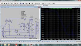
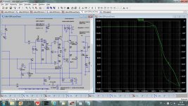
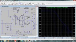
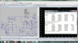
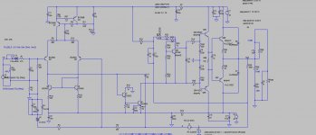
Here is my attempt with pur Cherry. I used my Little GEM as a start point. From look of the close loop gain it should be stable except strange kink at about 55MHz.
This kink is more visible in local stability simulation. simulation with .tran does not show any stability problem. I tried to tame that kink but at the moment with no success. Included zip file with all needed files, so if you like to try it and find better solution.
In my opinion pure Chery gives a bit lower distortion then TMC but not easy to tame.
Best Regards Damir
Attachments
-
 local-stability.jpg240.9 KB · Views: 247
 -
 CLG.jpg238.8 KB · Views: 233
 -
 LG-1.jpg232.6 KB · Views: 219
 -
 LG-2.jpg244.4 KB · Views: 225
 -
 THD20k-20Vpp.jpg207.9 KB · Views: 224
 -
little GEM-pureChery.zip17.3 KB · Views: 52
-
 overload.jpg177.7 KB · Views: 77
 -
 square-imputfilter.jpg180.5 KB · Views: 76
 -
 square-noimputfilter.jpg182.1 KB · Views: 80
Thanks for this Damir. It won't be until sometime next week before I can do some work on this but in the meantime, try decoupling your VAS emitter resistor R17 with 1n or less.Here is my attempt with pur Cherry. I used my Little GEM as a start point. From look of the close loop gain it should be stable except strange kink at about 55MHz.
This kink is more visible in local stability simulation. simulation with .tran does not show any stability problem. I tried to tame that kink but at the moment with no success. Included zip file with all needed files, so if you like to try it and find better solution.
It's good to do this looking at the Nyquist of your Inner Loop. This is good whenever you are tweaking stability. You need to expand the region around (0,0) & (-1,0)
___________________
BTW, LTspice has a good 'Copy bitmap to Clipboard' under 'Tools'. You can paste this into Paint and save a nice PNG or GIF of either your curves or circuit without extra rubbish.
I find it very difficult to read your schematics.
___________________
Yes. The VERY BEST TMC versions can get to within 6dB of 'pure Cherry' THD20k. In fact only you have achieved this. Most of the others are about 20dB worseIn my opinion pure Chery gives a bit lower distortion then TMC but not easy to tame.
Even then, you'll see the THD residual is a lot less spiky (less High Order Harmonics) with 'pure Cherry'.
I'm hoping this thread will help people tame it.
I feel the techniques are just not as well known. This thread has helped crystallize my thoughts and I'll write more later.
Last edited:
BTW, LTspice has a good 'Copy bitmap to Clipboard' under 'Tools'. You can paste this into Paint and save a nice PNG or GIF of either your curves or circuit without extra rubbish.
I find it very difficult to read your schematics.
Here is my attempt with pur Cherry. I used my Little GEM as a start point...
Hi Damir
I really like your work but it is so hard to read.
I add my request to please make it easier for people.
And you will receive better feedback too
Best wishes
David
Dadod, try removing the RC's at the VAS output before you add the degeneration decoupling.
Also, concerning the decoupling. Pay attention to the Rm*C corner frequency. It should probably be higher then the ULGF. Rm is emitter resistance and is 27mV/Iq for the VAS. This may help if the sizing of this cap is a bit ambiguous.
Also, concerning the decoupling. Pay attention to the Rm*C corner frequency. It should probably be higher then the ULGF. Rm is emitter resistance and is 27mV/Iq for the VAS. This may help if the sizing of this cap is a bit ambiguous.
Thanks for this Damir. It won't be until sometime next week before I can do some work on this but in the meantime, try decoupling your VAS emitter resistor R17 with 1n or less.
It's good to do this looking at the Nyquist of your Inner Loop. This is good whenever you are tweaking stability. You need to expand the region around (0,0) & (-1,0)
___________________
BTW, LTspice has a good 'Copy bitmap to Clipboard' under 'Tools'. You can paste this into Paint and save a nice PNG or GIF of either your curves or circuit without extra rubbish.
I find it very difficult to read your schematics.
___________________
Yes. The VERY BEST TMC versions can get to within 6dB of 'pure Cherry' THD20k. In fact only you have achieved this. Most of the others are about 20dB worse
Even then, you'll see the THD residual is a lot less spiky (less High Order Harmonics) with 'pure Cherry'.
I'm hoping this thread will help people tame it.
Hi kgrlee,
I know how to get better readable shematic, but here the point was on the plots and how I've got it, and I attached .asc and models files so it's easy to open it and see the schematic.
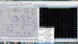
I tried decoupling VAS resistor and the best result I've got with 220pF, but still that kink at 55MHz was there.
BR Damir
Hi Damir
I really like your work but it is so hard to read.
I add my request to please make it easier for people.
And you will receive better feedback too
Best wishes
David
Thanks David,
Here is schematic for those who don't use LTspice.
BR Damir
Attachments
Dadod, try removing the RC's at the VAS output before you add the degeneration decoupling.
Also, concerning the decoupling. Pay attention to the Rm*C corner frequency. It should probably be higher then the ULGF. Rm is emitter resistance and is 27mV/Iq for the VAS. This may help if the sizing of this cap is a bit ambiguous.
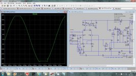
Keantoken, without RC's at the VAS output it's got berserk.
Strange when I repeated the simulation there was that glitch at 55MHz no more, some simulation artifact??
Here are close loop simulations with and without 220pF parallel to the VAS degeneration resistor.
Damir
Attachments
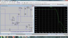
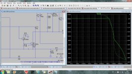
You can try 47R+220p RCs across the output BCs as shown in Cordell's book.
A total of 440pF capacitance at the VAS output shows that the VAS gain is having to be greatly reduced in order to achieve stability, which seems to defeat the purpose of this type of compensation.
A total of 440pF capacitance at the VAS output shows that the VAS gain is having to be greatly reduced in order to achieve stability, which seems to defeat the purpose of this type of compensation.
You can try 47R+220p RCs across the output BCs as shown in Cordell's book.
A total of 440pF capacitance at the VAS output shows that the VAS gain is having to be greatly reduced in order to achieve stability, which seems to defeat the purpose of this type of compensation.
I tried that too, but with 220pF, 47pF is not enough. Electrically that is the same as connection from bases to the ground and LTspice shows exactly the same result, but probably in real PCB it is better solution.
P.S. I used predrivers across BCs connected 220pF ceramic cap, in my TT amp, and that tamed triple OPS.
Last edited:
I guessed the info was in the plots but what is the plot for?Hi kgrlee,
I know how to get better readable shematic, but here the point was on the plots and how I've got it, and I attached .asc and models files so it's easy to open it and see the schematic.
I try to give very specific names to my plots & explicitly explain them in the post. I detail the EVERY change I make to a circuit if I don't post it. When I think the changes are too many to easily understand, I post another clean circuit.
And white background is good too.
It's all about communication. I missed your first recommendations for TMC in #55 cos I found it too hard to understand your plots. As Dave says, the clearer your presentation, the more likely you are to have good feedback.
Also its good if any .ASC you post will run AS IS without modification. It is very confusing to a SPICE newbie like me to have to modify stuff just to get things running.
Most people are likely to give up immediately .. so no feedback.
---------------------
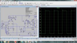
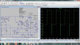
I haven't time to investigate further but try connecting up your C2 330p at the input and also shorting out V4 your input sine generator.I tried decoupling VAS resistor and the best result I've got with 220pF, but still that kink at 55MHz was there.
BR Damir
This is essential when looking at stability of main or inner loops.
The 50MHz kink is there with other (or even NO) compensation schemes too.
I'm hoping some people will try 'pure Cherry'. 10x better distortion is worth a little (OK a LOT
I have run minor loop gain sims of your beloved Cherry circuit with my models and the loop is still unstable.
As I noted previously, it's enclosing the output stage singularities within the Miller loop that causes the instabiltiy, regardless of the type of output stage.
In other words, the second stage continues generating gain greater than unity long after the output stage poles have taken effect; this causes greater than 180 degrees phase shift long before unity loop gain frequency is reached.
Thus, Cherry's output inclusive compensation is simply unworkable without fairly draconian shunt compensation at the second stage's output as I have previously established.
I guessed the info was in the plots but what is the plot for?
I try to give very specific names to my plots & explicitly explain them in the post. I detail the EVERY change I make to a circuit if I don't post it. When I think the changes are too many to easily understand, I post another clean circuit.
And white background is good too.
It's all about communication. I missed your first recommendations for TMC in #55 cos I found it too hard to understand your plots. As Dave says, the clearer your presentation, the more likely you are to have good feedback.
Also its good if any .ASC you post will run AS IS without modification. It is very confusing to a SPICE newbie like me to have to modify stuff just to get things running.
Most people are likely to give up immediately .. so no feedback.
---------------------
I haven't time to investigate further but try connecting up your C2 330p at the input and also shorting out V4 your input sine generator.
This is essential when looking at stability of main or inner loops.
The 50MHz kink is there with other (or even NO) compensation schemes too.
If you put the cursor on the plot picture and keep it for a wile it will show the name of the plot. I am trying to use names as clg(close loop gain), lp(loop gain), local-stability, thd20k and so on. I hope that help. I am not sure if you know that after you expand attached picture, in the lower left corner there is some kind of a square(Expand to actual size) and if you right click on it the picture will expand further. I’ll try to be more descriptive in the future.
I prefer black background for a plots as it shows the colors better(it is with reason chose by Linear Technology as default). In my plots I keep part or whole schematic together with the plot to be more clear what kind of the plot it is. Maybe it’s not so good idea as it shrinks the graph?
All .asc files I attached I do in zip file together with all needed models files. I f you expand it in the same directory you can run it without any modification.
If you read my further post about that glitch(kink) at 55MHz it looks that it was something with LTspice. When I closed LTspice and opened it again there it disappeared.
BR Damir
Michael, how about running MY models?I have run minor loop gain sims of your beloved Cherry circuit with my models and the loop is still unstable.
.. loadsa dubious pontificating ..
Thus, Cherry's output inclusive compensation is simply unworkable without fairly draconian shunt compensation at the second stage's output as I have previously established.
It's very easy to take someone else's circuit, make major changes & substitutions and muck it up completely. You have shown several times that you are a true master at this.
When you do this, you don't prove the other person's circuit is bad. You just prove you know how to muck up someone else's circuit. We totally concede this point.
What is your point? Is it that everyone else's circuits are rubbish? If so, how about posting some of your own ideas which are obviously superior to our rubbish so we can learn something?
Michael, how about running MY models?
I don't trust your models. You can lead a horse to water...
Here is a link to the post with your models:
The ZTX1056A/796A are relatively slow with their 500p/220p Cbe. This is completely different from using something like the 2SC3501/A1381.
I used Zetex models for the input stage and the TIS. These are also attached, together with the models for the drivers and the output stage; you can compare them with your models.
The ZTX1056A/796A are relatively slow with their 500p/220p Cbe. This is completely different from using something like the 2SC3501/A1381.
- Status
- This old topic is closed. If you want to reopen this topic, contact a moderator using the "Report Post" button.
- Home
- Amplifiers
- Solid State
- TPC vs TMC vs 'pure Cherry'