Presentation:
I am going to describe a new class of hybrids, a Composite of Vacuum tubes and semiconductors having remarkable properties.
The OPT in tube amplifiers is one of the main sources of problems: even the best generate non-linearities, they are costly, very specific, and their parasitic parameters severely limit the amount of feedback that can safely be applied to combat the said non-linearities.
Tube sound is one thing, "magnetic" sound is something completely different and rather unpleasant: it generates odd harmonics at a low level because of the sigmoid transfer function.
Benefiting from the tube sound without the unpleasantness of the magnetic sound is certainly worthwhile, and those having listened to OTL amps report a greater transparency, unachievable by other means.
How it works?
C-Vac is essentially a high precision current multiplier, using a low power tube (or other device) as a model. The virtual tube resulting from the multiplication process is the exact copy of the model, just very much larger: instead of mA's, the anode current becomes amperes, but the curves remain absolutely identical, apart from the scale factor.
The scale factor can range from 1 to many thousands without accuracy loss, and the dynamic performance extends to tens of MHz.
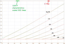
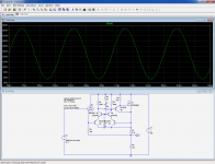
Below is an illustration of the faithfullness of the multiplication: the green curves are the reference scaled by the correct factor to enable comparison, and the red ones belong to the substitute based on the same 12AT7 tube.
The curves are almost perfectly overlaid, except at low voltages where divergences appear.
These divergences are caused by the fact that the substitute uses a enhancement device, requiring a minimum voltage to begin to conduct, and there are no auxiliary bias sources or connections.
But this also means that the substitute can be used in any configuration or topology, without restriction.
Anyway, circuits using tubes in the linear domain normally provide a minimum A-K voltage, and if this low voltage issue really is a problem, there are easy workarounds with auxiliary bias connections.
From the red curves, we can see that this virtual tube is in fact equivalent to 303 paralleled 12AT7 triodes: the C-Vac circuit acts as an exoskeleton boosting the "muscles" of its "pilot":
The resulting composite device is totally dominated by its tube model, the semiconductor part being almost ideally transparent and neutral.
Of course, purists are bound to say that "it cannot possibly sound like a real tube", but all the others will see it as a sensible and realistic approach, combining the best of both worlds.
I have posted this subject in the Solid State section, because C-Vac is completely based on semiconductors, but I will also describe a real application example, an OTL amplifier in the Tubes section.
To be continued....
I am going to describe a new class of hybrids, a Composite of Vacuum tubes and semiconductors having remarkable properties.
- Many hybrid schemes end up in an unhappy marriage, combining the flaw of one technology with the inconvenience of the other.
- On the contrary, C-Vac is designed with a well-defined goal in mind: generate near-ideal substitutes of vacuum tubes using a "model" tube and semiconductor circuitry.
The OPT in tube amplifiers is one of the main sources of problems: even the best generate non-linearities, they are costly, very specific, and their parasitic parameters severely limit the amount of feedback that can safely be applied to combat the said non-linearities.
Tube sound is one thing, "magnetic" sound is something completely different and rather unpleasant: it generates odd harmonics at a low level because of the sigmoid transfer function.
Benefiting from the tube sound without the unpleasantness of the magnetic sound is certainly worthwhile, and those having listened to OTL amps report a greater transparency, unachievable by other means.
How it works?
C-Vac is essentially a high precision current multiplier, using a low power tube (or other device) as a model. The virtual tube resulting from the multiplication process is the exact copy of the model, just very much larger: instead of mA's, the anode current becomes amperes, but the curves remain absolutely identical, apart from the scale factor.
The scale factor can range from 1 to many thousands without accuracy loss, and the dynamic performance extends to tens of MHz.
Below is an illustration of the faithfullness of the multiplication: the green curves are the reference scaled by the correct factor to enable comparison, and the red ones belong to the substitute based on the same 12AT7 tube.
The curves are almost perfectly overlaid, except at low voltages where divergences appear.
These divergences are caused by the fact that the substitute uses a enhancement device, requiring a minimum voltage to begin to conduct, and there are no auxiliary bias sources or connections.
But this also means that the substitute can be used in any configuration or topology, without restriction.
Anyway, circuits using tubes in the linear domain normally provide a minimum A-K voltage, and if this low voltage issue really is a problem, there are easy workarounds with auxiliary bias connections.
From the red curves, we can see that this virtual tube is in fact equivalent to 303 paralleled 12AT7 triodes: the C-Vac circuit acts as an exoskeleton boosting the "muscles" of its "pilot":
An externally hosted image should be here but it was not working when we last tested it.
The resulting composite device is totally dominated by its tube model, the semiconductor part being almost ideally transparent and neutral.
Of course, purists are bound to say that "it cannot possibly sound like a real tube", but all the others will see it as a sensible and realistic approach, combining the best of both worlds.
I have posted this subject in the Solid State section, because C-Vac is completely based on semiconductors, but I will also describe a real application example, an OTL amplifier in the Tubes section.
To be continued....
Attachments
Last edited:
The simplest form of such a device is the CFP, the 'input' device dictates the characteristics. To get proper multiplication one needs to work on the way the 'output' device is interfaced, somewhat more complex than just a resistor in the collector/drain/anode circuit of the reference device ")
Knowing the author's previous work, I am very much looking forward to this thread!
Knowing the author's previous work, I am very much looking forward to this thread!
After the appetizers, here is some real meat
Let us begin to examine some circuits.
Many implementations are possible and have been evaluated, I have selected the ones offering the best performance to complexity ratio.
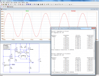
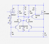
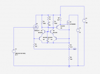
In C-Vac1, the cathode current of the "pilot" is sensed by R2, and compared to the boosted current by a Rush cascode, compensated by Q3 and Q4.
The circuit is used in a follower and a "naked" tube is also shown for reference.
The boosting factor is set by the ratio of R2 to R1, in this case 303x.
The loads are in the same ratio, yielding 30.3K for R3.
For a complete accuracy, the 100Ω sense resistor is also included.
In general, the circuits where the tube has to be virtualized will already use some degeneration, and thus the sense resistor can be made part of it.
If there is no degeneration, the sense resistor can be made smaller, it is a tradeoff between the sensing accuracy and the deviation from a non-degenerated device.
100Ω for a low power triode is relatively insignificant and gives excellent accuracy with discrete transistors.
If the transistors are monolithic matched pairs, even greater accuracy can be achieved, allowing for lower values.
We can see that the two outputs are almost perfectly superposed.
The differences in the THD's are also insignificant, and the spectral signatures are similarly near-identical.
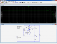
For this simple circuit, the frequency response is limited to only ~10MHz, but we will see later that this can be easily extended if required.
Note that a real circuit should also preferably include a gate stopper and a protection zener, but since their effect is negligible, they do not appear in the sim.
Let us begin to examine some circuits.
Many implementations are possible and have been evaluated, I have selected the ones offering the best performance to complexity ratio.
In C-Vac1, the cathode current of the "pilot" is sensed by R2, and compared to the boosted current by a Rush cascode, compensated by Q3 and Q4.
The circuit is used in a follower and a "naked" tube is also shown for reference.
The boosting factor is set by the ratio of R2 to R1, in this case 303x.
The loads are in the same ratio, yielding 30.3K for R3.
For a complete accuracy, the 100Ω sense resistor is also included.
In general, the circuits where the tube has to be virtualized will already use some degeneration, and thus the sense resistor can be made part of it.
If there is no degeneration, the sense resistor can be made smaller, it is a tradeoff between the sensing accuracy and the deviation from a non-degenerated device.
100Ω for a low power triode is relatively insignificant and gives excellent accuracy with discrete transistors.
If the transistors are monolithic matched pairs, even greater accuracy can be achieved, allowing for lower values.
We can see that the two outputs are almost perfectly superposed.
The differences in the THD's are also insignificant, and the spectral signatures are similarly near-identical.
For this simple circuit, the frequency response is limited to only ~10MHz, but we will see later that this can be easily extended if required.
Note that a real circuit should also preferably include a gate stopper and a protection zener, but since their effect is negligible, they do not appear in the sim.
Attachments
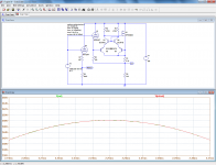
Let us go a bit deeper: the simple C-Vac1 circuit is accurate, has a good low-frequency behavior, but it also has a weakness: its dynamic performances.
The small signal frequency response is perfectible, but that is not where the problem really lies.
The main weakness is the large signal frequency response: it is caused by the large value of R4 and the Cgd capacitance of the MOS. Under large signal conditions, the current provided by R4 becomes insufficient to charge Cgd.
The 470K value just allows for a full swing at 20KHz, which in theory is sufficient for audio, but is a bit short to say the least.
Why not decrease R4 then? A tenfold reduction would mechanically push the full power bandwidth to 200KHz for example.
The reduction of R4 (and R3 which is linked to it) has a number of inconvenients: it increases the quiescent power, and it makes the virtual tube less perfect.
The resistors in themselves do not actually degrade the accuracy, because their current is returned via R1, and is thus taken into account in the tube simulation, but they put a lower limit to the cut-off current of the tube.
With 47K, the current could not go below ~13mA, and the additional quiescent dissipation at 150V would amount to ~1W.
None of that is catastrophic, and has to be put in perspective: the composite tube now has a maximum current of several amperes, and less than 15mA leakage is not going to degrade anything, and the 300V voltage used for the test is not realistic in an OTL context: I have kept the 300V value to allow for easy comparisons in a tube environment, but in the example, it leads to rather obscene power levels, almost 1kW peak in this case, much more with a speaker load.
Under more realistic conditions, the problems would be less severe, but anyway tackling them by brute force only is not the best solution.
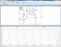
Adding a buffer stage will improve the small signal behavior and ~halve the current requirements, because R3 and R4 can remain of a relatively high value.
C-Vac2 shows an example: the small signal bandwidth is increased to ~50MHz, and it now accepts 100KHz at full power for a marginally increased dissipation and cut-off current. Compensation becomes necessary in this case.
More elaborate improvement schemes are possible, but they involve high voltage small signal transistors, an annoyance that has so far been avoided.
The small signal frequency response is perfectible, but that is not where the problem really lies.
The main weakness is the large signal frequency response: it is caused by the large value of R4 and the Cgd capacitance of the MOS. Under large signal conditions, the current provided by R4 becomes insufficient to charge Cgd.
The 470K value just allows for a full swing at 20KHz, which in theory is sufficient for audio, but is a bit short to say the least.
Why not decrease R4 then? A tenfold reduction would mechanically push the full power bandwidth to 200KHz for example.
The reduction of R4 (and R3 which is linked to it) has a number of inconvenients: it increases the quiescent power, and it makes the virtual tube less perfect.
The resistors in themselves do not actually degrade the accuracy, because their current is returned via R1, and is thus taken into account in the tube simulation, but they put a lower limit to the cut-off current of the tube.
With 47K, the current could not go below ~13mA, and the additional quiescent dissipation at 150V would amount to ~1W.
None of that is catastrophic, and has to be put in perspective: the composite tube now has a maximum current of several amperes, and less than 15mA leakage is not going to degrade anything, and the 300V voltage used for the test is not realistic in an OTL context: I have kept the 300V value to allow for easy comparisons in a tube environment, but in the example, it leads to rather obscene power levels, almost 1kW peak in this case, much more with a speaker load.
Under more realistic conditions, the problems would be less severe, but anyway tackling them by brute force only is not the best solution.
Adding a buffer stage will improve the small signal behavior and ~halve the current requirements, because R3 and R4 can remain of a relatively high value.
C-Vac2 shows an example: the small signal bandwidth is increased to ~50MHz, and it now accepts 100KHz at full power for a marginally increased dissipation and cut-off current. Compensation becomes necessary in this case.
More elaborate improvement schemes are possible, but they involve high voltage small signal transistors, an annoyance that has so far been avoided.
Attachments
Sorry for being frontal, but what is this crazy schematic?
1) R5 is 100 ohms and has 150V across it, it dissipates (idle) 225 Watts
Only possible in "Simulation World"; in any real bench you would be opening all room windows by now to clear the smoke.
2) you did not include or even mention any biasing for the tubes, only show an AC signal, which in the absence of any indication to the contrary, is to be presumed referenced to ground.
Care to elaborate?
Thanks
Attachments
Member
Joined 2009
Paid Member
There are many other things that make a tube amplifier what it is that may not be adequately captured by this replacement circuit but I love the concept - it's clever!
Things that I like about tubes - the fact that they are often low power means that the system is put together differently than a SS amp. The speakers have to be more sensitive and this alone makes many tube systems sound different from solid state. Tube amps are often linear enough not to require feedback and this changes things too - not leas their response to speaker back emf. Do you plan to try your circuit in an equivalent system, low power with sensitive speakers, no feedback and a choke loaded power supply ???
Things that I like about tubes - the fact that they are often low power means that the system is put together differently than a SS amp. The speakers have to be more sensitive and this alone makes many tube systems sound different from solid state. Tube amps are often linear enough not to require feedback and this changes things too - not leas their response to speaker back emf. Do you plan to try your circuit in an equivalent system, low power with sensitive speakers, no feedback and a choke loaded power supply ???
Woah, hold on there. Are you sure? Most tube amps I've heard without feedback were far from linear...Tube amps are often linear enough not to require feedback and this changes things too...
Sorry for being frontal, but what is this crazy schematic?
1) R5 is 100 ohms and has 150V across it, it dissipates (idle) 225 Watts
Only possible in "Simulation World"; in any real bench you would be opening all room windows by now to clear the smoke.
2) you did not include or even mention any biasing for the tubes, only show an AC signal, which in the absence of any indication to the contrary, is to be presumed referenced to ground.
Care to elaborate?
..... and the 300V voltage used for the test is not realistic in an OTL context: I have kept the 300V value to allow for easy comparisons in a tube environment, but in the example, it leads to rather obscene power levels, almost 1kW peak in this case, much more with a speaker load..
No, at the moment I have built a test amplifier, an OTL in class B of ~70W.Tube amps are often linear enough not to require feedback and this changes things too - not leas their response to speaker back emf. Do you plan to try your circuit in an equivalent system, low power with sensitive speakers, no feedback and a choke loaded power supply ???
The benefit of this circuit is precisely to get rid of the current limitations of normal tubes.
One could think oF a SE class A amplifier of the kind you describe, but with muscle enough to drive a standard loudspeaker directly and comfortably. That may be my next project.
The amplifier I have built has almost no feedback, because the open loop gain of the two ECC81 I have used (1 voltage amplifier, 1 phase-splitter and 2 in PP) is barely sufficient to get the full power output with 0.5Vrms in, yet the THD at 70W is under 0.5%. That would be difficult to achieve with semiconductors.Woah, hold on there. Are you sure? Most tube amps I've heard without feedback were far from linear...
Last edited:
The circuits described so far are completely "orthodox", and create a simple and faithful copy of the tube they emulate (except for the magnified currents).
It is possible to be more "creative", and to take advantage of the possibilities offered by the additional circuit.
The possibilities are infinite, but I will provide two examples that are probably the most logical and useful in this case.
It is often necessary to create a grid bias, using a cathode resistor or a similar arrangement. This can of course be duplicated in the case of C-Vac, but there is an advantageous alternative: instead of applying the bias to the complete composite, it can be inserted in the cathode of the low power tube alone.
The functional result is identical, but the power wasted is much lower.
I have used this trick in the SolidGlass example.
Another interesting possibility is to use separate supplies for the tube and the high current section.
This is a logical step in the context of OTL amplifiers, because tubes do not like to be starved of voltage, but high supply voltages generate uncomfortably high levels of power with standard speaker impedance's.
The best way to reconcile these conflicting requirements is to split the two supplies.
I didn't use this option in SolidGlass, and even with a 16Ω load the dissipation is quite daunting....
Attachments
Go and explain that to the tube guys, but just leave me enough time to find a safe place to hide...Not really necessary to multiply a non-linear current with such accuracy.
The loads of the SolidGlass gain stages are bootstrapped, which is a close approximation (and yields a relatively low THD with little FB).The most linear loadline for a triode is a flat line of constant current.
Gm is not linear, Mu is...
Well actually, the most linear voltage gain is a little beyond constant
into CCS + negative loadline land. Go there, and I will be impressed.
There are other applications for C-Vac: you can boost accurately any type of device, including semiconductors, a J-Fet for example. There are amplifiers using many small devices in parallel, with C-Vac you only need one pair.
Or if you want something really exotic, germanium transistors, a PA composed of 1,000 pairs of 2N45's for example.
You could also discard completely the silly input device, and just keep the C-Vac circuit alone: you'd be left with an ideal textbook Bjt, having constant, linear and accurately defined parameters like h21, and h11, zero Vbe or offset etc.
Associate one N and one P, and you have an ideal follower, without problems of Xover distortion, gm doubling and the kind....
To get good emulation of a triode, you need to keep the voltage feedback on it's plate accurate. So a constant current thru the triode will just give you a good V follower, not a triode response.
Splitting the supplies for tube and SS will help the efficiency, but not the tube sound faithfulness, since the output's voltage swing becomes less a factor for the triode's plate feedback.
I suggest some type of voltage multiplier for the tube plate feedback when splitting these two supplies.
Splitting the supplies for tube and SS will help the efficiency, but not the tube sound faithfulness, since the output's voltage swing becomes less a factor for the triode's plate feedback.
I suggest some type of voltage multiplier for the tube plate feedback when splitting these two supplies.
By applying 300V to the anode of the triode, you will simulate a triode amplifier with a 300V supply. It will have an output limited to +/- 20V perhaps, but is it really a problem? It will work in small signal conditions, almost at its best.Splitting the supplies for tube and SS will help the efficiency, but not the tube sound faithfulness, since the output's voltage swing becomes less a factor for the triode's plate feedback.
Using a supply of 30V for the same purpose will have the opposite effect, and what you propose is a sort of middle term.
OK, why not for the sake of truthfulness, but then resorting to an impedance-changing trick is probably overcomplicated and not necessary: pushing the "HV" supply to 60V (for example) to respect the relative excursion levels might be sufficient.
I am not expert enough in the tube field to decide, but I think that there is some sort of self-similarity at different voltage levels, provided you don't exceed the tube limits, which is not really a problem here, since you can arbitrarily decide at which current level the tube operates
Well, depends on what you want to accomplish I guess. Going for a small delta Vout from a 300 V supplied tube will be fairly linear. Maybe too linear to sound much different from an Op Amp. I was thinking of emulation of a tube output stage, where the output plates will generally be pushed within 60V of the cathode, and nearly 2X the B+ (using a P-P xfmr). As you suggested, (at least for a 3/2 power current tube model) self similarity would allow for operation of the "pilot" tube at reduced voltage and current. Real tubes may run into some linearity problems eventually at low enough current levels, due to leakage currents and grid structure end currents.
Not too hard to make a low current voltage multiplier with a HV Mosfet and some divider resistors, with some feedback driver. Another approach would be to use a small P-P xfmr for direct voltage transform from the output back to the "pilot" plates or screen grids.
A clever approach which has been previously used for tube emulation is to just take a good SS amp and use a tube in "reverse" in the global neg. feedback path. (CCS on its cathode, grounded grid, amplifier output cap. drives the plate, neg. amp feedback taken from the cathode, 1/Mu attenuation feedback) This gives a SE (single ended) tube amplifier emulation instead of a PP tube amp. emulation.
Another approach is to series a SS amp and a small tube amp at their outputs (with a very low output Z winding on the tube amp, like 0.1 Ohm). The SS amp runs normally with its internal resistive neg. global feedback. But the tube amp uses the summed output for its global feedback signal. Sort of a tube "veneer" added amp this way. Total sum looks like what the tube amp wants this way. Can also be looked at as a class G amp with the SS amp providing the tracking supply (thru the tube's OT).
Last edited:
A plate voltage feedback xfmr (from the output back to the "pilot" tube) could be just a 1:1 bifilar xfmr to get 2:1 overall voltage multiplication between the SS and tube supplies. This would provide phenomenal OT bandwidth and still provide a respectible voltage on the tube(s). Maybe just use an off the shelf 600:600 Ohm xfmr.
Edcor makes some 1:1 xfmrs (at least they seem to be bifilar when 1:1 ratio'd) XSM---- up to 15K:15K Ohm. Around $13 each.
Edcor makes some 1:1 xfmrs (at least they seem to be bifilar when 1:1 ratio'd) XSM---- up to 15K:15K Ohm. Around $13 each.
Last edited:
Smoking, the one transistor, one current sense resistor
(Sziklai pair method) *IS* using triode Mu for feedback.
Runaway of the sand is another matter to consider. With
a SE amp, and passive resistive load, controlled voltage
gain makes runaway of a simple Sziklai pair unlikely.
But you push pull against another boosted triode (Elvee
does this in another thread), you need at least one to set
a limit for current. Gm multiplier works well as any other
scheme. I'm not convinced its the simplest or best way...
--
If you want to go rail to rail, then you need something
more complicated. As you have to scale the feedback
across the plate-cathode to a lesser swing that keeps
reasonable voltage across the triode at all times. This
feedback cut is gonna boost the simulated Mu by the
same ratio, but should still behave triodishy...
Last edited:
- Status
- This old topic is closed. If you want to reopen this topic, contact a moderator using the "Report Post" button.
- Home
- Amplifiers
- Solid State
- A new hybrid concept: C-Vac