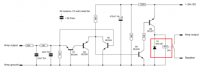
The zener will not do what you think. The diode is there to catch the EMF kickback the relay coil produces when it is de-energised. You have 24V across a 12V relay, which is why the coil is overheating.
The easiest solution here is to add a resistor in series with the relay. Measure the resistance of your relay's coil, then add a resistor that will drop the required power using the Voltage Divider formula. For example, if your relay's coil is 400 ohms, you would do R = ((24 * 400)/12) -400.
The easiest solution here is to add a resistor in series with the relay. Measure the resistance of your relay's coil, then add a resistor that will drop the required power using the Voltage Divider formula. For example, if your relay's coil is 400 ohms, you would do R = ((24 * 400)/12) -400.
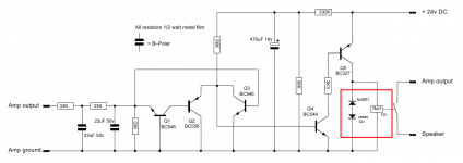
Even easier, since he's already got the 12V Zener - just put the Zener in series with the relay coil. That will drop the 24V down to 12V.The easiest solution here is to add a resistor in series with the relay.
Godfrey,
that makes the relay pull in very susceptible to variation in mains supply voltage.
In principle yes, but I don't think this will be a problem, as most relays pull in at approx. 85% and, once activated, remain in the on position down to even lower voltages.
I would worry more about the Zener diode passing approx. 100mA while dropping 12V, making for 1.2W dissipation. Not every small Zener diode will take that in free air.
Rundmaus
a 1W resistor should be adequate
Doubt that.
At least, the nominal relay coil current should be looked up and the actual dissipation in the series resistor should be calculated. If my rough estimate of 1.2W is right, I would at least use a 2W or even 3W resistor to avoid excessive surface temperatures.
Rundmaus

sofaspud, that would defeat the purpose of the catch diode, which is to prevent relay coil back-EMF destroying Q5.
I'd be surprised if the relay coil uses 100mA. I looked up a fairly typical relay for this job, a Finder 40.31 12V, which has a 220 ohm coil and that's 55mA. You could probably get away with 40mA of current and it'd pull in.
edit: Project16, what did you measure for the resistance of your relay's coil?
Last edited:
The relay is an Omron G2R 2, the resistance of the coil is 275 ohms (manufacturer specific).edit: Project16, what did you measure for the resistance of your relay's coil?
OK, well because you are going from 24V to 12V that makes things easy - ideally, you want a 275 ohm resistor, but the closest are 270 ohms and 220 ohms.
If we go with 270 ohms, that is 270+275 = 545 ohms. At 24v this gives us 24/545 = 0.044A (44mA).
The power dissipated in our resistor will be P=I^2R = (0.044*0.044)*270 = 0.523W - as you can see, a half watt resistor will be rather hot ! A 2W resistor is best for safety.
A 220 ohm resistor will also work just as well, there will only be slightly more current flowing which will not damage the coil.
I saw my use of the zener to be (while reverse-biased) holding the relay coil at 12V. It then becomes the catch diode for back-EMF (while forward-biased). It does double duty.sofaspud, that would defeat the purpose of the catch diode, which is to prevent relay coil back-EMF destroying Q5.
sofaspud, actually there's an interesting article on Rod Elliot's page about using a Zener to limit back EMF. The important thing is that it does not slow the opening speed of the contacts. However it's not used as a way to run a lower voltage coil on a higher voltage. I'm not sure what the implications of that are, but I wouldn't want to recommend a mod that might degrade the function of the DC protection.
- Status
- This old topic is closed. If you want to reopen this topic, contact a moderator using the "Report Post" button.
- Home
- Amplifiers
- Solid State
- relay coil that heats.