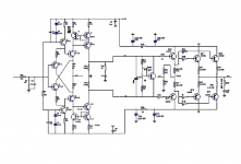
3) a current is injected: 24V/33000 ohms (not discounting the roughly 0.6V diode drop because we already have enough precision as-is)=0.72mA
4) We may safely assume it's evenly split between both parallel BE diodes, so 2SC2240 gets 0.36mA into its base.
Fahey, I thought that way too, but the situation is actually somewhat different. The (base:collector)-to-emitter voltage will be "around" 0.5 volts because of Hfe (my write-up above, estimates 350 Hfe, average). Thus, since collect-to-emitter current flow is Ib x Hfe even at low voltages, then Ib must be Ic/Hfe ... which is to say 0.72 mA / 350 = 2 uA or so. Working backward from the curve is impossible ... since we can't see 2 uA, so instead just rely on the e^(ktdV/T0) PN junction characteristic: Vbe should be about 0.48V to achieve 2 uA current, and therefore, 0.72 mA of quiescent given the 33K pull-up Rc. Now... keep with me here - 0.48V is also nominally on the base of the compliment. The current flow at the collector of the compliment is Hfe2/Hfe1 related to the current flow of the leftmost transistor. If they're the same, then 0.72 mA flows. If the Hfe ratio is 3x in favor of the right transistor, then 3x0.72 = 2.3 mA flows. The "system" though is hypersensitive to thermal mismatch and Hfe mismatch between the transistors. (all four of them!) This would be a near-nightmare circuit to get working right.
Sorry to be so detailed... but in this case, the devil is between the sheets.
Datasheets, that is.
GoatGuy
not to become crazy
the shortcut on the Chinese product ebay
http://www.ebay.com/itm/Diamond-buf..._Audio_Amplifiers_Preamps&hash=item337df4c697
I've posted before
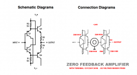
is a version of CFB Marantz
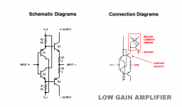
this is The ideal scheme to set a very low gain ratio
because it is very stable and have low open loop gain
the aim is to get the maximum gap between the gain without feedback (open loop)
and the gain set by feedback
without the system oscillates
I can not explain better
I repeat that the theme of my research is the gain value set
I discovered a sublime sound with this method
: Cavaliere:
do not miss this information with the calculations
someone check the sound on his amplifier
the shortcut on the Chinese product ebay
http://www.ebay.com/itm/Diamond-buf..._Audio_Amplifiers_Preamps&hash=item337df4c697
I've posted before
is a version of CFB Marantz
this is The ideal scheme to set a very low gain ratio
because it is very stable and have low open loop gain
the aim is to get the maximum gap between the gain without feedback (open loop)
and the gain set by feedback
without the system oscillates
I can not explain better
I repeat that the theme of my research is the gain value set
I discovered a sublime sound with this method
: Cavaliere:
do not miss this information with the calculations
someone check the sound on his amplifier
Attachments
Last edited:
the shortcut on the Chinese product ebay
Diamond Buffer Input CFB High Speed Power Amplifier Stereo | eBay
I've posted before
is a version of CFB Marantz
this is The ideal scheme to set a very low gain ratio
because it is very stable and have low open loop gain
the aim is to get the maximum gap between the gain without feedback (open loop)
and the gain set by feedback
without the system oscillates
I repeat that the theme of my research is the gain value set
I discovered a sublime sound with this method
: Cavaliere:
do not miss this information with the calculations
someone check the sound on his amplifier
Exactly follows the definition of trolling, feed him and it will never stop. Which I'm just doing
 .
.the devil is between the sheets.
Datasheets, that is.
GoatGuy
That's the point.
We read and *use* the datasheets for useful purposes; Stee uses Photoshop to clip garbage all over the place, edit parts values out (so they can't be simulated and proved wrong
), couple it to a picture of 1947 nurses listening to some 78rpm records, another picture of some undisclosed and unrelated Audio device, invent some bogus product name and post it as a Big Invention.
You guys make lousy art critics. Forget the numbers and calculations. Just sit back, relax, and enjoy the imagery.Fahey,
(or step outside, if you feel a sudden urge to barf)

An externally hosted image should be here but it was not working when we last tested it.
Last edited:

 .. this thread
- Status
- This old topic is closed. If you want to reopen this topic, contact a moderator using the "Report Post" button.
- Home
- Amplifiers
- Solid State
- the Golden Gain Ratio