Hi,
I wrote to you a few weeks ago ( http://www.diyaudio.com/forums/solid-state/232770-25w-mosfet-amp-troubleshooting.html ) asking for advice on fixing my first 'relatively big' project. It was a 25W Class AB amp taken from redcircuits.
I already followed every advice given on the thread. I changed all the input stage transistors and the output mosfet's without any real progress.
Even though I pretend to leave the board on the 'to-do' box, I would really like to start looking for alternatives.
It is kind of mandatory to stick with the same power source (most of the money invested on the project went to the power TR and the box for the amp). It's specs are 220: 25-0-25 120Watts giving after rectifying aprox. ±37V without load.
I have been searching on the solid state and pass labs forums and the most viable option is the symAsym5. ( SymAsym5 - Project ). Even though I would have to change a few transistors it looks doable taking into account my country's lack of offer in transistors..
I'm looking for some advice on other ~15-20W, preferible Class AB amps.
(I was discouraged to build anything else from redcircuits in my other thread). As a sidenote most of the ICs for the ChipAmps I found here (and also for most class D amps on this forum) are unavailable here, whereas mosfets outputs allow me to adapt much better to the bill of materials).
Thank you!
The GT-101 might be a good project for you. The biggest problem is that shipping to Uruguay is rather expensive, around $90.00.
If you have enclosures and transformer available locally, you could just buy the circuit boards and parts kits, with or without heatsinks. The shipping then becomes quite affordable, owing to the greatly reduced weight.
Many people have successfully built the kit.
Akitika GT-101 Audio Power Amplifier Kit
The GT-101 might be a good project for you. The biggest problem is that shipping to Uruguay is rather expensive, around $90.00.
If you have enclosures and transformer available locally, you could just buy the circuit boards and parts kits, with or without heatsinks. The shipping then becomes quite affordable, owing to the greatly reduced weight.
Many people have successfully built the kit.
Akitika GT-101 Audio Power Amplifier Kit
I am trying to avoid kits since it's quite hard to buy them from my country. (the delay due the shipping is about 2-3 months..)
This afternoon I'm going to start visiting the electronic's stores from here to check if they have everything I need for giving the symasym5.3 a test. Do you have any idea if it's possible to supply it with my TR?
Under load it's supposed to give about 33-34v so the output should be a little bit less than the 60W proposed by the designer. Therefore, do you think a TR rated for 120VA will do the job?
120 VA transformer can't deliver enough current for 60W per channel. In general losses will limit the usable output to about 1/2 the transformer rating... EE? do the math... its good practice,...do you think a TR rated for 120VA will do the job?
")
Why not build a Circlophone? I just made one and it was a very fun project with excellent results:
http://www.diyaudio.com/forums/soli...tion-parts-accessories-beginner-friendly.html
http://www.diyaudio.com/forums/soli...tion-parts-accessories-beginner-friendly.html
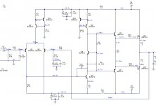
Perhaps repurposing what you already have there would be a good route to go. The RedCircuit is very poor, but with a few changes and a minimum of added parts you can make a respectable amp. The biggest flaws seen with the RedCircuit is the lack of temperature compensation for the outputs, the way the output mosfets are driven and the value choices of frequency shaping components that have the bass and treble both severely rolled off at each end.
Attachments
Last edited:
120 VA transformer can't deliver enough current for 60W per channel. In general losses will limit the usable output to about 1/2 the transformer rating... EE? do the math... its good practice,
My question was about if taking for granted a 50% efficiency on the symasym was on the safe side. I am totally aware that I'm getting a mono amplifier.
Why not build a Circlophone? I just made one and it was a very fun project with excellent results:
Being the Circlophone a class A (..AA?) amp, going with a 34v@8ohm build for a 65ish Watt output, wouldn't it draw a lot more than 120VA from the power source?
http://www.diyaudio.com/forums/soli...tion-parts-accessories-beginner-friendly.html
With ±37V, you could build a cascoded F5 and keep the bias low enough for whatever heat sinks you have.
A F5 is rated for a 180VA power consumption, wouldn't a cascoded one go for a much higher consuption?
My first guess was that I was tied to a class AB amp due to the 'high' voltage // low power TR.
Perhaps repurposing what you already have there would be a good route to go. The RedCircuit is very poor, but with a few changes and a minimum of added parts you can make a respectable amp. The biggest flaws seen with the RedCircuit is the lack of temperature compensation for the outputs, the way the output mosfets are driven and the value choices of frequency shaping components that have the bass and treble both severely rolled off at each end.
Thank you a lot for your answer!
I did speak to one of my electronics teacher and he was quite intrigued about how the mosfet's were driven. I believe that what you draw was a lot more alike to what he descrived as usual.
Mounting both mosfets on the same heatsink shouldn't compensate their behaviour? Should some kind of thermally depending component be added to the feedback path?
Q6 in my schematic is the bias generator and thermal compensation device. It would be mounted on the heatsink between the mosfets. Adjustment of R5(1k pot) adjusts the idle current in the mosfets.
I have not yet studied mosfet's and how to drive them yet, so I am planning to stick with your proposed design for the new build.
I am quite upset about how awfully was the LP filter from the input stage calculated. Thank you a lot for pointing that to me!
Why did you change the cap from the high pass filter too? The pole was at about 7Hz which seemed fine. Also, can the electrolytic cap operate with the reversed polarity shown on the diagram?
- Status
- This old topic is closed. If you want to reopen this topic, contact a moderator using the "Report Post" button.
- Home
- Amplifiers
- Solid State
- Advice on choosing a new ~20W Project