We have to do some careful measurments and tests now. I suspect that this might be down to slight differences in Vbe (the turn on voltage) of the newer transistors (which isn't a problem).
The DC voltage on L1 is correctly adjustable and swings positive and negative when VR1 is adjusted... yes")
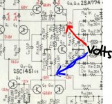
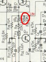
With VR2 at minimum resistance measure and record the DC voltage across TR11 and D6 as shown.
Now turn up VR2 to maximum resistance and again measure and record the DC volts as shown.
(Its much more accurate measuring this way across the Vbe multiplier than measuring voltages from ground)
The DC voltage on L1 is correctly adjustable and swings positive and negative when VR1 is adjusted... yes
With VR2 at minimum resistance measure and record the DC voltage across TR11 and D6 as shown.
Now turn up VR2 to maximum resistance and again measure and record the DC volts as shown.
(Its much more accurate measuring this way across the Vbe multiplier than measuring voltages from ground)
Attachments
Transformer update
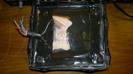
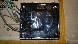
I finished fixing the transformer but I made a mess... I glued it to the floor
After two hours I ended up removing the floor but as soon as my grandmother find out about it I'm death eheheheh
At least after all this troubles the transformer look a lot better
I finished fixing the transformer but I made a mess... I glued it to the floor
After two hours I ended up removing the floor but as soon as my grandmother find out about it I'm death eheheheh
At least after all this troubles the transformer look a lot better
Attachments
We have to do some careful measurments and tests now. I suspect that this might be down to slight differences in Vbe (the turn on voltage) of the newer transistors (which isn't a problem).
The DC voltage on L1 is correctly adjustable and swings positive and negative when VR1 is adjusted... yes
With VR2 at minimum resistance measure and record the DC voltage across TR11 and D6 as shown.
Now turn up VR2 to maximum resistance and again measure and record the DC volts as shown.
(Its much more accurate measuring this way across the Vbe multiplier than measuring voltages from ground)
VR2 min, voltage across TR11 and D6 3.35V, voltage at R1 -6mv
VR2 max, 3.70V, R1 -2.2mv
Voltage at R1 don't swing but stay constant, 0mv between pin 9-13 and VR1 always at minimum
I After two hours I ended up removing the floor but as soon as my grandmother find out about it I'm death eheheheh
At least after all this troubles the transformer look a lot better
Your still here to tell the tale... for the time being
VR2 min, voltage across TR11 and D6 3.35V, voltage at R1 -6mv
VR2 max, 3.70V, R1 -2.2mv
Voltage at R1 don't swing but stay constant, 0mv between pin 9-13 and VR1 always at minimum
R1... you mean L1, the output. You have to be clear and careful in all you do
So VR2 is swinging the voltage across the Vbe multipier (and diode) from 3.35 to 3.7 volts. That's a good result and it shows its working OK, just that its a little "out of range" to bias the output stage. We'll come back to that a little later.
For now set VR2 back to minimum resistance such that the voltage across TR11/D6 is at its minimum.
VR1. That should swing the voltage on L1 from slightly positive to slightly negative as it is turned. From what you have just written that is not happening so re check that adjustment works OK.
Your still here to tell the tale... for the time being
R1... you mean L1, the output. You have to be clear and careful in all you do
So VR2 is swinging the voltage across the Vbe multipier (and diode) from 3.35 to 3.7 volts. That's a good result and it shows its working OK, just that its a little "out of range" to bias the output stage. We'll come back to that a little later.
For now set VR2 back to minimum resistance such that the voltage across TR11/D6 is at its minimum.
VR1. That should swing the voltage on L1 from slightly positive to slightly negative as it is turned. From what you have just written that is not happening so re check that adjustment works OK.
Yes sorry I mean L1, I will be more carefull about it.
The voltage on L1 don't go positive whatevere setting I use for VR1-2, the video show L1 after turning on the amp, VR1-2 at minimum.
If I touch either VR1 or 2 it goes more negative
Video - TinyPic - Free Image Hosting, Photo Sharing & Video Hosting
Check that VR1 is working properly. If you measure at Q1-B (Base) and adjust VR1, it should swing + & -
The two diodes, D2/3 clamp to ~ +/-0.6V which in turn sets the offset V.
If you measure DCV across Q1/2 collectors you should see it change from slightly positive to slightly negative as VR1 is adjusted. This indicates that VR1 is working correctly. There will be a null point where Q! & Q2 are conducting equally or the bias current is in balance.
There probably is some inter-action between adjusting VR1 and VR2
I'd go along with that
Hopefully there isn't a problem, its just puzzling that the offset doesn't adjust. It could be related to the fact the output stage is drawing zero current. I would be content for now just to know that the voltage on the wiper of the pre-set adjusts to plus 0.6 ish volts and minus 0.6 ish volts as the pre-set is turned.
With the output stage currently drawing zero current there is a "dead zone" around the zero point.
If the above checks OK then I think we should move on
Attachments
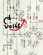
This is what I suggest as the next step. The bias generator TR11 is developing 3.7 volts maximum. That is failing to turn on the combined base and emitter junctions of outputs, drivers and pre driver. That's 6 B-E junctions that need to be forced into conduction and if we say 0.65 volts is needed per junction (its around that figure give or take...) then we need nearer 3.9 volts.
So what I propose is to remove R33 and then starting with VR2 on minimum resistance slowly adjust it and see if you can get the output stage to draw current. You should then be able to get a voltage between test points TP9 and 13 (the output). Remember the voltage is small. If it adjusts OK then carefully see if it will reach around 50 millivolts. The bulb will probably begin to glow.
So what I propose is to remove R33 and then starting with VR2 on minimum resistance slowly adjust it and see if you can get the output stage to draw current. You should then be able to get a voltage between test points TP9 and 13 (the output). Remember the voltage is small. If it adjusts OK then carefully see if it will reach around 50 millivolts. The bulb will probably begin to glow.
Attachments
I read in another forum some guy picked up a Pioneer SX-1980 in the junk yard, of course it has issues & the guy stated he ain't no expert, I shall follow the thread for a bit. As you can see this thread is becoming a book on fixing/re-building a nice amp. I think the Pioneer EE would be proud.Molly you're a rock star mate and gde3- you have my respect for your dedication in amplifier resuscitation. If this was House M.D they'd have called time of death a hundred posts ago....great going, and I'm rooting for you from a long way away!
For this one, it is making forward progress, since Molly is the navigator.
I agree with the the dead zone idea.
Make the measurements, set the bias up a bit and adj offset again.
Cheers
Folks
I'd go along with that
Hopefully there isn't a problem, its just puzzling that the offset doesn't adjust. It could be related to the fact the output stage is drawing zero current. I would be content for now just to know that the voltage on the wiper of the pre-set adjusts to plus 0.6 ish volts and minus 0.6 ish volts as the pre-set is turned.
With the output stage currently drawing zero current there is a "dead zone" around the zero point.
If the above checks OK then I think we should move on
the voltage is -22.15, now I will try to remove R33
Sorry Mooly, name sp. mistake that I can not correct!!
where?
Hopefully not this one unless you mean mV?
?the voltage is -22.15, now I will try to remove R33
where?
Hopefully not this one unless you mean mV?
You should then be able to get a voltage between test points TP9 and 13 (the output). Remember the voltage is small. If it adjusts OK then carefully see if it will reach around 50 millivolts. The bulb will probably begin to glow.
Last edited:
Sorry Mooly, name sp. mistake that I can not correct!!
No problem
It happens more than you might think.There was a short with a big spark between pin 7 and 9 and now the board don't work anymore. Not sure how that happen, call it inexperiece or just bad luck but unfortunately this is the situation. Probably at the moment I'm too depressed but I think that this project just ended up badly
At worst you have probably zapped the lower PNP output and maybe its driver but we now go back to basics and do a few checks.
1) With it switched OFF make sure that the rails are discharged.
2) Measure on "low ohms range" or on the "diode" range on your meter across collector and emitter of both the output transistors. If one or both read short then that transistor is zapped.
3) Do the same for both driver transistors Q20 and Q21
4) Check that all the 0.5 ohm resistors are OK.
5) Check that both the 4.7 ohm resistors (R69 and R70) that feed the output transistors are OK
6) Check that R65 and R66 are OK. These are the 22 ohm resistors that feed the driver transistors.
7) Make sure the fuses in the power supply are OK.
Report back with what you find.
- Status
- This old topic is closed. If you want to reopen this topic, contact a moderator using the "Report Post" button.
- Home
- Amplifiers
- Solid State
- Help repairing Pioneer M3