I just want to make sure which method is the correct one for winding a toroid. Which of the 2 versions I have below is the correct one? This would be used for a smps. Transformer would need to be center tapped, using 4 windings each as an example. Thanks for the help.
Version 1
Version 1
Attachments
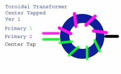
For low power you can use version 1 to reduce capacitance between winding at the expense of having worse coupling bwtween them and double the leakage inductance
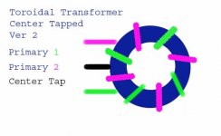
For high power version 2 is desirable due to better coupling at high frequencies and optimum leakage inductance
To optimize the winding for high power you should also select a proper volts/turn ratio, the higher you can [less turns mean less wire resistance and less leakage inductance] but mantaining some security margin to prevent the core to saturate at high temperatures
Cores tend to have higher permeability at higher temperatures, storing more energy in the same time period, and reduced energy energy storage capaability as temperature increases so they are much easier to saturate when hot
Phasing!
If both the free ends of the windings pass through the centre of the toroid the same direction as per the drawing, they will be in phase. This is not what you want for a centre tapped winding. Apply ac between the ends of the windings and it will behave like a short cct. The beginning of the winding should go through from one side and the end should exit from the opposite side.
If both the free ends of the windings pass through the centre of the toroid the same direction as per the drawing, they will be in phase. This is not what you want for a centre tapped winding. Apply ac between the ends of the windings and it will behave like a short cct. The beginning of the winding should go through from one side and the end should exit from the opposite side.
- Status
- This old topic is closed. If you want to reopen this topic, contact a moderator using the "Report Post" button.
- Home
- Amplifiers
- Solid State
- Winding a Transformer