Hi all,
This is my first post here, so here goes...")
The other week I picked up a nice Kenwood KA-3500 40watt intergrated amplifier in pretty good shape.
Upon using it a bit more, I noticed a bit of distortion at high volume, more so in the left channel. I checked the DC offset at the speaker terminals, and the L channel said 100 mV, while the R was 25 mV. I understand this isn't so good for the L channel at least, but unfortunately this amp doesn't have any DC offset adjustments. Am I right in saying that to fix this I'd have to replace the output transistors?
--
On a related issue, I'm a bit confused about the BIAS adjustment In the service manual I found the section on BIAS adjustment, and I read online how it can affect the DC offset. So I hooked up my voltmeter to the test points, and I got 4 mV on the L, and 8 mV on the R. In the manual it says should be 40 mV.....(!). Is there something wrong here? I tried carefully adjusting them, but they only go to 30mV with the pots fully on, this doesn't seem right to me.
--
I compromised at 23 mV BIAS for both channels, and now the DC offset is 40 mV for L, and 10 mV for R, which is better, less than half what they were. I'm wondering, will I damage anything doing this, should I put them back to where they were?
The amp does seem to actually sound better, less distortion, though it still distorts at moderate to high volume. I felt the chips, and they weren't getting hot.
Another thing I noticed is that when it starts distorting, the BIAS voltage drops to near zero. Would this indicate the power trasistors, or the BIAS supply?
If I were to replace the output transistors, what would you recommend as substitutes? They are 2 each of NEC 2sb618 and 2sd588.
--
I've attached the service manual and owner's manuals as RAR files (rename them from zip to rar). The owner's manual actually has a better schematic than the shop manual, all on one page. I've also included some pictures. They're not my actual unit, but mine is exactly the same, just less dusty..... They are actually RAR files, even though they say ZIP, as this was the only way I could upload them, so please RENAME them to RAR after download. Hope this isn't a problem, maybe they'll help out someone else as well........
Thanks for reading this, hope it wasn't too long. Many thanks in advance, looking forward to posting here in the future!
All the best,
Bellarmine
This is my first post here, so here goes...
The other week I picked up a nice Kenwood KA-3500 40watt intergrated amplifier in pretty good shape.
Upon using it a bit more, I noticed a bit of distortion at high volume, more so in the left channel. I checked the DC offset at the speaker terminals, and the L channel said 100 mV, while the R was 25 mV. I understand this isn't so good for the L channel at least, but unfortunately this amp doesn't have any DC offset adjustments. Am I right in saying that to fix this I'd have to replace the output transistors?
--
On a related issue, I'm a bit confused about the BIAS adjustment In the service manual I found the section on BIAS adjustment, and I read online how it can affect the DC offset. So I hooked up my voltmeter to the test points, and I got 4 mV on the L, and 8 mV on the R. In the manual it says should be 40 mV.....(!). Is there something wrong here? I tried carefully adjusting them, but they only go to 30mV with the pots fully on, this doesn't seem right to me.
--
I compromised at 23 mV BIAS for both channels, and now the DC offset is 40 mV for L, and 10 mV for R, which is better, less than half what they were. I'm wondering, will I damage anything doing this, should I put them back to where they were?
The amp does seem to actually sound better, less distortion, though it still distorts at moderate to high volume. I felt the chips, and they weren't getting hot.
Another thing I noticed is that when it starts distorting, the BIAS voltage drops to near zero. Would this indicate the power trasistors, or the BIAS supply?
If I were to replace the output transistors, what would you recommend as substitutes? They are 2 each of NEC 2sb618 and 2sd588.
--
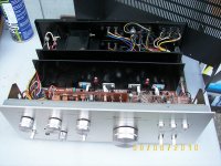
I've attached the service manual and owner's manuals as RAR files (rename them from zip to rar). The owner's manual actually has a better schematic than the shop manual, all on one page. I've also included some pictures. They're not my actual unit, but mine is exactly the same, just less dusty.....
They are actually RAR files, even though they say ZIP, as this was the only way I could upload them, so please RENAME them to RAR after download. Hope this isn't a problem, maybe they'll help out someone else as well........Thanks for reading this, hope it wasn't too long. Many thanks in advance, looking forward to posting here in the future!
An externally hosted image should be here but it was not working when we last tested it.
All the best,
Bellarmine
Attachments
-
 KenwoodKA-3500100_2747.JPG98.3 KB · Views: 1,479
 -
Pictures.zip709.7 KB · Views: 168
-
Kenwood KA-3500 Service Manual.part1.zip732.4 KB · Views: 189
-
Kenwood KA-3500 Service Manual.part2.zip343 KB · Views: 130
-
Kenwood KA-3500 Owners Manual.part1.zip976.1 KB · Views: 105
-
Kenwood KA-3500 Owners Manual.part2.zip976.1 KB · Views: 86
-
Kenwood KA-3500 Owners Manual.part3.zip976.1 KB · Views: 79
-
Kenwood KA-3500 Owners Manual.part4.zip976.1 KB · Views: 85
-
Kenwood KA-3500 Owners Manual.part5.zip976.1 KB · Views: 82
-
Kenwood KA-3500 Owners Manual.part6.zip834.9 KB · Views: 98
Your approach/conclusion is absolutely wrong ....thinking replacing the outputs of this amplifier to cure the specific problem sounds like a car that has an obvious engine problem and your idea is to replace the wheels ....
Outputs are transistors not tubes .... on off condition only either work or not ...
for a unit of the age the first thing you do is to replace all small capacitors
some info can be found here
http://www.diyaudio.com/forums/solid-state/136261-vintage-amplifier-repair-upgrade-manual.html which is probably worthless if you cannot follow procedure ...
Kind regards
sakis
The DC offset of 100 mv is nothing to worry over at this stage. Historically offset values have fallen as designs have improved.
To set the bias current you MUST have no speakers connected because any DC offset affects the reading. Adjust for 20 millivolts across either of the 0.47 ohm resistors or 40 millivolts across the two together. Page 4 in the manual shows it clearly. Recheck the reading as the amp warms and err on the low rather than high side.
The distorted audio sounds like some other issue and as Sakis mentions, electrolytic caps could be suspect.
The correct way to fix this is to use a scope and see what is actually going on. Without a scope its all guesswork. Bias current issues will not cause distortion at high volume.
Hello Sakis & Mooly,
Thank you very much for your replies!
You're probably right about the electrolytic caps being worn out, I'll have to look into that.
I was following the recommendations at this page, if I understand correctly, they seem to be saying that above 50mV DC offset is not good, and recommend replacing the input differential pairs to fix it :
Amplifier Distortion, DC-Offset, and You! - AudioKarma.org Home Audio Stereo Discussion Forums
You're right about it being nonsensical replacing the output transistors without reason. I got mixed up, I apologize, I meant the input differential pairs. That's interesting what you say about the output transistors either working or not. So they generally can't be 'partially' fried? I didn't know that......
I did read the shop manual about the BIAS adjust, and hooked up my meter to the transistor legs as shown, and made sure the speakers were disconnected. Am I right in saying that it should be 40mV BIAS per channel? Again, I can't get it above 30mV per channel turning the pots all the way up.....??
Anyway, again many thanks for the help. My Dad does have an oscilloscope, I was hoping it might be something simple or easy (guess I should know better.... ) When I get the chance, I'll look into checking it out more thoroughly. As you say, maybe replacing a couple of capacitors will solve the problems. For the time being I could just use it as a preamp, just finished wiring in a set of pre-out jacks, so I could use it that way, and it sounds great at low to medium volume.......
All the best Sakis & Mooly, and kind regards!
Bellarmine
Thank you very much for your replies!
You're probably right about the electrolytic caps being worn out, I'll have to look into that.
I was following the recommendations at this page, if I understand correctly, they seem to be saying that above 50mV DC offset is not good, and recommend replacing the input differential pairs to fix it :
Amplifier Distortion, DC-Offset, and You! - AudioKarma.org Home Audio Stereo Discussion Forums
You're right about it being nonsensical replacing the output transistors without reason. I got mixed up, I apologize, I meant the input differential pairs. That's interesting what you say about the output transistors either working or not. So they generally can't be 'partially' fried? I didn't know that......
I did read the shop manual about the BIAS adjust, and hooked up my meter to the transistor legs as shown, and made sure the speakers were disconnected. Am I right in saying that it should be 40mV BIAS per channel? Again, I can't get it above 30mV per channel turning the pots all the way up.....??
Anyway, again many thanks for the help. My Dad does have an oscilloscope, I was hoping it might be something simple or easy (guess I should know better....
) When I get the chance, I'll look into checking it out more thoroughly. As you say, maybe replacing a couple of capacitors will solve the problems. For the time being I could just use it as a preamp, just finished wiring in a set of pre-out jacks, so I could use it that way, and it sounds great at low to medium volume.......All the best Sakis & Mooly, and kind regards!
Bellarmine
If you have a DC off set of more than say 20mV then there is a problem with the amplifier, possibly leaky capacitors.
The Quiescent current is what you are adjusting, not the offset!
Adjust with care and set the voltage to 20mV if you are measuring across one of the R47 resistors or 40mV if between the emitters. Make this adjustment when the amplifier is warm.
The Quiescent current is what you are adjusting, not the offset!
Adjust with care and set the voltage to 20mV if you are measuring across one of the R47 resistors or 40mV if between the emitters. Make this adjustment when the amplifier is warm.
very common failure also for these age of amplifier is somewhere one resistor is open or the value drifted to something else . Caused from exposure to heat or moisture for a long period of time .
Combine the two things together and the picture goes more to there since both bias and offset fails to meet the original specs .
Truly though the first step is the electrolytics and then the resistors .
your remark about the first stage transistor is also correct and since many manufacturers like to run them quiet hot ( performance is better like this)
No trouble there choose anything you like for a new pair ... and a wise choice will alter the performance of the amplifier for a lot better
Find out from the service manual the original specs of the transistors which also include the hfe grade choose something that is close or a bit higher
ft and bandwidth can be higher and amp will benefit from that but no lower in any case than the original
Power ratings should be alike and that is not critical but operating voltage should be as low as the original device ( that can be trouble IE to match all teh above specs in a brand new semi )
Finally all of these type of amplifiers will benefit from very very closely matched front end transistors and if possible thermally coupled .
Do not underestimate the original transistors if working ok do not replace them Japanese always made proper choice of semis both in specs and quality .
Finally you have to work with caution if something goes wrong and you blow the outputs these are absolutely unobtainable . Many available and even better replacements ( more rugged and faster ) exist but the housing is very different and for sure the bias scheme will not fit and will require modifications ..
Kind regards
Sakis
This kind of thing is very difficult without having the unit to work on... its odd that the bias current stated in the manual is not obtainable.
I would advise first of all to check some the basics, don't overlook anything.
Are the supplies correct ? That's the -/+ 40 volts to the output stage. Just thinking that the voltage selector might be set incorrectly.
If both channels are behaving identically then this points to a common issue rather than an individual component fault.
Check all the supplies are correct first.
I referred to this schematic at Hi-fi engine. It's certainly an old design from about 1972, I think. I noticed weird darlington current limiters in there (Q9-16)and the caps used to smooth their action are probably useless if they haven't been replaced by now, along with others that may be having a bearing on the signal at high levels and the bias range.
Even if it only serves as refurbishment, replace C15,16, 21-24 and 33 if it's not already been done. These are all inexpensive 47uF values. You can replace every cap. in one hit of course, but you learn nothing that way.
It's interesting that offset is affected by bias - odd circuit operation.
Even if it only serves as refurbishment, replace C15,16, 21-24 and 33 if it's not already been done. These are all inexpensive 47uF values. You can replace every cap. in one hit of course, but you learn nothing that way.
It's interesting that offset is affected by bias - odd circuit operation.
Thank
Thanks Ian for that improved service manual, better schematic in it. Those caps you mentioned are pretty easy to replace, guess I could try 'em first. According to HIFI Engine, it's from 1977. I don't understand too well what you're saying about the Darlingtin pairs, I'm pretty new to this. I've read a few mini-booklets, but guess I should do some more studying into basic Electronics.
So you're saying Sakis, maybe check the BIAS resistors, but replace the electrolytic caps first. Guess I should only replace the first stage after checking the caps and resistors.
When I get some time, I'll check out the supply voltage first Mooly, guess that would explain the under-spec BIAS.
I can understand what you mean about not having the unit to work on. I'm helping a fellow in Australia wire up his Johnson outboard, would be so much easier if I was just there. Wired up one myself, see my website for a movie just for fun.......:^)
Thanks again Harleyjon, Sakis, Mooly & Ian, this is just great. Wish I could find a lot more time to tweak and learn, my Dad's an electrical engineer, had gobs of time when he was younger, but now has even less than me (groan)...:^)
All the best!
Bellarmine
- Status
- This old topic is closed. If you want to reopen this topic, contact a moderator using the "Report Post" button.
- Home
- Amplifiers
- Solid State
- Kenwood KA-3500 Integrated Amp DC Offset / BIAS Adjust confusion