Shunt regulators are typically used to power low-powered Class A stages, which in all my measurements, do draw constant current. Please explain yourself Andrew. your arguments are not making sense here.
Hi cotdt.
You should measure that again... just put a 1 .. 10 ohm resistor in series between the last PSU capacitor and the class A stage, and place a scope across the resistor. Play some bassy music.
You will see a voltage modulated by the audio signal - this means the current is not constant.
You can also see this if you draw the load line of the stage...
The *average* current drawn by the class A stage is constant, not the instant current!
Thank you. Yes this is obvious basic electronics, and it would have been nice if the person making the arrogant statements could have just explained it the way that you did.
Two circuits for discussion
Hello,
Please forgive me to reopen this old thread.
I'm looking for the best yet simple regulator to feed a TDA1543 @ around 5.2V
I'm looking for low Impedance, Low noise, low cost
The voltage source is a 3S LiPo Battery Pack 11.1V.
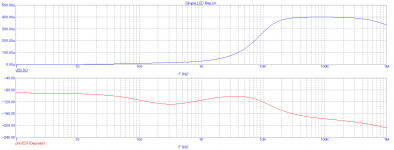
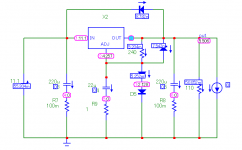
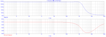
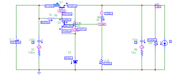
Here are two designs, one serie using the venerable LT317 as Voltage Serie Regulator and one using a discreet Shunt regulator along with their respective Zout.
Please could you comment on which one would you pick and why or eventually propose an other option taking into acount the cost issue.
Hello,
Please forgive me to reopen this old thread.
I'm looking for the best yet simple regulator to feed a TDA1543 @ around 5.2V
I'm looking for low Impedance, Low noise, low cost
The voltage source is a 3S LiPo Battery Pack 11.1V.
Here are two designs, one serie using the venerable LT317 as Voltage Serie Regulator and one using a discreet Shunt regulator along with their respective Zout.
Please could you comment on which one would you pick and why or eventually propose an other option taking into acount the cost issue.
Attachments


Since TDA1543 is a dual 16-bit DAC, I think your decision to use a linear regulator is appropriate. You don't want high frequency SMPS artifacts on the supplies of your DAC.
I recommend choosing the shunt regulator topology, but with two changes: (i) use a TO220 packaged device for the PNP shunt transistor Q2, so you can get the heat out. (ii) size the two 45R input resistors for the worst case scenario: battery is 99% discharged AND the DAC is drawing its maximum possible current, driving two full amplitude 20 kHz sinewaves.
I recommend choosing the shunt regulator topology, but with two changes: (i) use a TO220 packaged device for the PNP shunt transistor Q2, so you can get the heat out. (ii) size the two 45R input resistors for the worst case scenario: battery is 99% discharged AND the DAC is drawing its maximum possible current, driving two full amplitude 20 kHz sinewaves.
to save on battery power I suggest you consider a switching Buck regulator.
This is a good idea, but also consider a SEPIC topology which can be work with equal input and output voltage, and is capacitively isolated from input power lines, so no risk of input to output short circuit (Except a bad cap). Any sim`ple driver as UCC3804 will perform excellent, and using coupled inductors ripple is very little at input and outputs lines.
For battery operation I would recommend a series regulator. The shunt regulator will draw the rated current all the time.
Note that a slow drift in the power rail, while difficult to filter, is also difficult to hear.") If you were using an ADC or DAC for precision measurements, fine, but in an audio context, who cares?
If you were using an ADC or DAC for precision measurements, fine, but in an audio context, who cares?
Note that a slow drift in the power rail, while difficult to filter, is also difficult to hear.
If you were using an ADC or DAC for precision measurements, fine, but in an audio context, who cares?No. Series elements and shunt elements are equally 'in the signal path'.mszerg said:My guess of the main difference between shunt vs series regulator is that shunt is not on the signal path (assuming its path starts from PSU), while in case of series you always have +1 component on the signal path.
Good point. However, as the TDA1543 is fussy about resistor values vs supply rail voltage (at least when used for resistor I/V in a typical NOS DAC) you don't want the voltage changing too much.SamAnytime said:Note that a slow drift in the power rail, while difficult to filter, is also difficult to hear.
Thank you for your suggestions.
At first, I didn't want to use switching Reg, as I fear that It will not sound as good although I could filter with a gyrator.
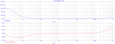
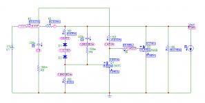
Let me propose a third schematic, a very simple discrete Serie to compare with The LT317 Serie and the Discrete Shunt.
It is the one that draws the most current, and has the highest output impedance at 0.18 Ohm. Possibly, also it is noisier ?
What do you think ?
At first, I didn't want to use switching Reg, as I fear that It will not sound as good although I could filter with a gyrator.
Let me propose a third schematic, a very simple discrete Serie to compare with The LT317 Serie and the Discrete Shunt.
It is the one that draws the most current, and has the highest output impedance at 0.18 Ohm. Possibly, also it is noisier ?
What do you think ?
Attachments
-
 Serie Reg PSU.png16.8 KB · Views: 102
 -
 Discrete Shunt Reg PSU Output Impedance.png18.2 KB · Views: 107
 -
 Discrete Shunt Reg PSU.png13 KB · Views: 107
 -
 Discrete Serie Reg PSU Output Impedance.png18.1 KB · Views: 116
 -
 Discrete Serie Reg PSU.png20.3 KB · Views: 268
 -
 Serie Reg PSU Output Impedance.png18.4 KB · Views: 97
SamAnytime, Don't you think that the DAC will always draw around 50 mA as per the data sheet ?For battery operation I would recommend a series regulator. The shunt regulator will draw the rated current all the time.
So here, the current draw will allways be about the same whatever the regulator type.
Hello,
Thank you for your answers.
Let me try to go a little bit deeper in my global project.
The Project is an all in one Mono portable audio system.
It includes a Raspberry Pi that sends mono and inverted mono to one (balanced) TDA1543 I2S nos DAC with passive I/V and active VRef.
The TDA is direct coupled to a TDA7391LV (11V1 /15 Watt into 3.2 Ohm Amplifier) in balanced Bridge mode.
The amplifier is connected to a small 3" full range speaker.
The complete system is 1.5L in size.
The goals are : the best sound for the lowest count parts at the lowest cost.
So compromises have to be done.
I will make a dedicated thread when everything is finished.
Right now I'm using a Anker Pro Lipo Power Bank that delivers 3x 5V along with 9/12V.
The system is running fine for hours on this bank.
The amplifier gets its 12V direct from the Bank.
The Raspberry Pi gets 5V from one USB port.
The DAC gets 5V from a second USB port.
I have also tested the system on a 2x 5V Power Bank
One 5V port (2100 mAh -> DC-DC 9V -> TDA7391LV)
One 5V port (1000 mAh -> Raspberry Pi and TDA1543)
Based on these tests I want to build my own powerbank / Battery managment and take the opportunity to build better PSUs for the TDA1543 / Vref.
Hence my questions above.
I have a new one thinking about Battery.
All these Power Banks use 3.7V batterry cells and DC-DC converters to get 5V.
This provides a security against battery voltage drop.
So I will use 3x 3.7V 2300 mAh cells, this makes 11.1V / 2300 mAh.
What is the best strategy :
My initial approach:
#1 11.1V -> AMP (The TDA7391LV can work down to 6V)
|_> Linear Regulator (which one ? LT317) -> DAC and Vref
|_> LDO 5V for the Raspberry Pi
Or
#1 11.1V -> DC-DC -> 12V + Gyrator and then feed the amp
|_> Linear Regulator (which one ? LT317) -> DAC and Vref
#2 11.1V -> DC-DC -> 5V for the Raspberry Pi
Or
#1 11.1V -> DC-DC -> 12V + Gyrator and then feed the amp
#2 11.1V -> DC-DC -> 8V -> LDO 5V for the Raspberry Pi
|_> Linear Regulator (which one ? Discrete Shunt) -> DAC and Vref
Any other strategy taking into acount best sound, low parts count (space is limited) and cost.
Thank you for your advises
Jean
Last edited:
Ok, my initial solution is bad because too inefficient (power loss).
Same for Solution 2 and 3.
SO:
#1 11.1V -> AMP (The TDA7391LV can work down to 6V)
#2 11.1V -> DC-DC -> 5V for the Raspberry Pi
#3 11.1V -> DC-DC -> 7V-> Linear Regulator (Shunt) -> DAC and Vref
OR
#1 11.1V -> DC-DC -> 12V + Gyrator and then feed the amp
#2 11.1V -> DC-DC -> 5V for the Raspberry Pi
#3 11.1V -> DC-DC -> 7V-> Linear Regulator (Shunt) -> DAC and Vref
Other option, add one cell and put to 2S packs in parallel.
7,4V @ 4600 mAh
#1 7.4V -> DC-DC -> 12V + Gyrator and then feed the amp
#2 7.4V -> Linear Regulator (Shunt) -> DAC and Vref
LAST option (similar to the one I'm using now)
3 cels in parallel (3P pack).
#1 3.7V -> DC-DC -> 12V + Gyrator and then feed the amp
#2 3.7V -> DC-DC -> 5V for the Raspberry Pi
#3 3.7V -> DC-DC -> 7V+ Gyrator -> Linear Regulator (Shunt) -> DAC and Vref
Thank you for your input
Jean
No. Series elements and shunt elements are equally 'in the signal path'.
Agreed...If it has an "error amplifier" it's in the signal path.
If the error amplifier is not low THD, distortion artifacts appear on the supply rails.
Taking into acount large current variation if I'm not using Pre DC-DC regulation, I have banned the shunt.
So, taking cost and space into consideration, the options, for the complete system are now :
3 cells in serie 3S pack (around 30€)
#1 11.1V -> AMP (The TDA7391LV can work down to 6V)
-> Linear Regulator (SERIE) -> DAC and Vref
#2 11.1V -> DC-DC -> 5V (XRP7659 : 1,2€) for the Raspberry Pi
OR if it really needs 12V to the amp, then, I would add One cell
2x 2S packs in parallel: 7,4V @ 4600 mAh (around 40€)
#1 7.4V -> DC-DC -> 12V (TPS61088 : 5,81€) + Gyrator
and then feed the amp
and -> Linear Regulator (SERIE) -> DAC and Vref
#2 7.4V -> DCD-DC -> 5V (XRP7659 : 1,2€) for the Raspbery Pi
Back to the serie regulator.
Does it make sense to replace the 2 green diodes at the Adj pin of the LT317
with a 4.096 V voltage reference LM4040A41IDBZT @ 2,53€.
The Dynamic impedance should again improve vs 2 leds
BUT What about noise ?
There is also the MAX6126A41+
Here, Noise should also improve but price is high @ 5,29€
Any audible improvement ?
Last edited:
The regulators (shunt or series, doesn't matter) control the output voltage. The noise and transient response are governed by the capacitor(s) on the output of the regulators. The 317 IIRC gives you an output 1.2V higher than the voltage at the adj pin. How you derive that voltage is up to you. A simple resistor will do in a pinch, but bias current drift will show in the output. If you are concerned about reference noise, bypass that also with a suitable capacitor.
Very important fact - thank you.One unique advantage of shunt reg. is that it prevents the circuit being powered from dynamically loading the supply, consequently removing A.C. currents from the ground return paths.
I also estimate this (except, when there are unwanted oscillation).Some even think that all ClassA amplifiers/stages draw constant current.
It's fallacies like this that lead unthinking builders down the route of sonic disasters.
What is wrong on this consideration ?
This I will check next time.Hi cotdt.
You should measure that again... just put a 1 .. 10 ohm resistor in series between the last PSU capacitor and the class A stage, and place a scope across the resistor. Play some bassy music.
You will see a voltage modulated by the audio signal - this means the current is not constant.
You can also see this if you draw the load line of the stage...
The *average* current drawn by the class A stage is constant, not the instant current!
Last edited:
- Status
- This old topic is closed. If you want to reopen this topic, contact a moderator using the "Report Post" button.
- Home
- Amplifiers
- Solid State
- Regs - Shunt vs Series