Following the nice discussion about the NMC (nested Miller compensation) amplifier, I have made an effort to better understand structures with multiple feedback loops. These ar e.g. TMC, EC, MIC, and NMC. As prototype, I have used TMC.
View attachment 345127
The current result is: We do not get the nice results suggested by common-sense arguments if the ULGF of the nested loops lie in the same regions. But this is the case with TMC and NMC. The OPS in the most inner loop will see an ULGF that roughly amounts to the *sum* of all surrounding feedback loops.
Thus, the TMC explanation that the NFB input point just shifts between OPS and VAS output, does underestimate the problem.
A real disaster happens with multiple NMC, where the hope of low ULGF around the OPS is completely unrealistic.
If the ULGF of the inner loop is much higher than that in the outer one, as e.g. with OPS EC and with MIC, the problem is of much less practical concern.
Best regards,
Matze
PS. Here is the LTspice input file.
View attachment 345128
That's a lot of work!!
I will try to understand it.
BTW, There is a new methodology to achieve extreme low THD, I just realized recently.
In normal concept, we overlook the input stage. We try to maximum the GNFB to let input stage have tons of extra gain to do the error correction. Under this concept, we come up TPC. That concept has its limitation. The input stage is pretty slow. You will find it just as slow as output stage, normally it will contribute a second pole just around 10MHz. It is pretty slow if you have 30MHz output device. It is not suitable for high speed performance.
The new methodology is to use TMC. It is a kind of negative feedback including output stage, without input stage. I come up 2 points to achieve extreme low THD under TMC. See below.
1. Using fast output stage. Thus, you can pump up transitional frequency of TMC. The transitional frequency can be much higher than ULGF.
2. High linear VAS with high gain. Normal EF enhanced VAS has enough gain, but it is not linear enough. I simulated a modified VAS. The amp can achieve THD 0.6ppm@1K.
As my understanding, your Nested Miller Compensation is some kind of TMC, getting some feedback without input stage.
Last edited:
Following the nice discussion about the NMC (nested Miller compensation) amplifier, I have made an effort to better understand structures with multiple feedback loops...
Just had a quick look and am impressed by the quick work!
Very minor correction - It is Mason's rule, not Manson's.
Manson is most famous as the name of a mass murderer
Have you had a look at RD Middlebrook's website?
Lot's of useful stuff on how to simply circuit analysis.
www.rdmiddlebrook.com
Best wishes
David
Following the nice discussion about the NMC (nested Miller compensation) amplifier, I have made an effort to better understand structures with multiple feedback loops.
OK. I mentioned this on Bob's thread but it is probably easier to discuss it here.
The transconductance of G2 looks about 10 times too low.
Seems a bad idea to pick an unrealistic value.
It would be better to use a realistic value between 1m and 10m and see what component values you need in the TMC circuit.
The point is that realistic values make it easier to compare a simulation or calculation with past experience to determine if it is plausible.
Best wishes
David
Last edited:
Hi David,OK. I mentioned this on Bob's thread but it is probably easier to discuss it here.
The transconductance of G2 looks about 10 times too low.
Seems a bad idea to pick an unrealistic value.
It would be better to use a realistic value between 1m and 10m and see what component values you need in the TMC circuit.
The point is that realistic values make it easier to compare a simulation or calculation with past experience to determine if it is plausible.
Best wishes
David
thank you for the comments and the kind words in earlier posts.
In order to keep the circuit as simple as possible, I just included the global feedback network of Bob's example (purely resistive, ratio 1/20) into G2. Using a G2 transconductance of 2mS and adding the GNFB network should not change anything else.
Best regards,
Matthias
Combination of TMC, NMC and TPC
Thinking about combination of different compensation schemes, I found a version that combines transitional Miller compensation (TMC), nested Miller compensation (NMC) and two-pole compensation (TPC). Maybe, this can be of interest also for other designs.
The example below uses ULGFs of around 1 MHz in the global NFB loop and the two nested loops (TMC, NMC), and a total ULGF of around 2 MHz seen by the output stage (OPS). This leads to sub-ppm THD-20 figures e.g. at 1V and 10V output voltage into 4 Ohms.
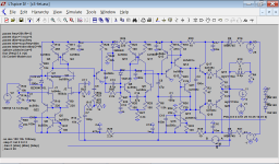
The schematic is a standard amplifier with TMC and cascoded FET input, if one removes the intermediate stage with Q7 to Q11 and the intermediate feedback path via C7 and C9.
Now first assume that C7 and C10 (near the base of Q8) are very large. Then an amplifier with one nested Miller compensation stage would result. In this case, the voltage division with R40/R41 could be skipped, and the transconductance of the stage with Q8/Q9 could be reduced by increasing R25/R26. This combination of TCM and one NMC loop results in single-ppm THD-20 values.
The linearity of the input stage (IPS) does not allow to further improve or stabilize this result, so simply adding more NMC stages does not bring very much. But it is possible to apply two-pole compensation around the IPS, so that its distortion is reduced. This is done by C7 in the intermediate feedback path. It reduces the load seen by the IPS at lower frequencies. Like in a TPC scheme for the "voltage amplifier stage" (VAS), this shifts feedback towards the IPS, but removes the same amount of feedback from the enclosed stage. So it is possible to increase the transconductance of the enclosed stage at lower frequencies, where the feedback is shifted to the IPS. This is done by the divider R40/R41/C10, saving at least 20dB of feedback in the inner loop. The zero produced by R41*C10 normally should be at the same frequency as the pole produced by (R17+R20)*C7, in the example it is roughly at the double frequency.
The amplifier turns on and off without disturbing transients that could be related to the only conditional stability. Since the constant-current source Q15/Q16 is faster activated than the rest of the circuit, a short peak via the negative rail voltage occurs via turn-on and off. This can be simply suppressed with clamping diodes at the OPS input, which have to be activated by some control circuitry during turn-on and off.
Clipping behaviour of the circuit could be better. After returning from saturation, it needs some microseconds to properly continue to work, but the circuit seems to remain stable during that process.
THD-20k 0.25W/4R: 0.25 ppm
THD-20k 25W/4R: 0.39 ppm
OPS Iq: 80mA
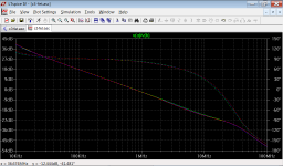
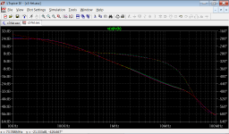
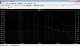
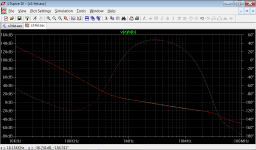
Below, I have placed the schematic, the loop responses of TMC loop, intermediate loop, loop around IPS, and total feedback around OPS.
Kind regards,
Matthias


Hi Matthias
Nice to see some more ideas from you.
Kind of late over here so I will look more carefully tomorrow.
Just one point, the simple V(a)/V(b) technique is OK for a loop with a very low source impedance, like the OPS.
For other loops it is more accurate to use a Tian Probe.
This is documented in one of the LTSpice loop gain examples.
Or there are examples in DIYAudio.
I have a simple double probe that I wrote to see outer and inner loops simultaneously.
A quick search of my recent(ish) posts to Paul "MCD99" should find it, otherwise I can send it to you.
Best wishes
David
Last edited:
Hi Matthias
Nice to see some more ideas from you.
Kind of late over here so I will look more carefully tomorrow.
Just one point, the simple V(a)/V(b) technique is OK for a loop with a very low source impedance, like the OPS.
For other loops it is more accurate to use a Tian Probe.
This is documented in one of the LTSpice loop gain examples.
Or there are examples in DIYAudio.
I have a simple double probe that I wrote to see outer and inner loops simultaneously.
A quick search of my recent(ish) posts to Paul "MCD99" should find it, otherwise I can send it to you.
Best wishes
David
Hi David,
thank you for the prompt comments.
Need to admit: with respect to compensation complexity, I do not hesitate ...
With respect to measurements in simulation, well, it is different ...
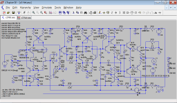
To my defence, I only can say that all Middlebrook probes are driven by the output, i.e. at most 9 Ohms, and are driving at least a kOhm.
Here is how I measured the TMC loop response:
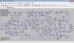
The same for the response of the intermediate loop:
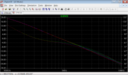
For some reason, Ltspice sometimes shifts phase by 360 degrees. Here is a plot of the region only between 100 kHz and 10 MHz:
Measurement of the loop around IPS:
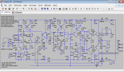
Finally, the total NFB around OPS:
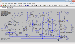
Kind regards,
Matthias
Need to admit: with respect to compensation complexity, I do not hesitate ...
Kind regards,
Matthias
Hi Matthias,
I like your style.
It's good to see some experimental compensation schemes.
Will have a look at .asc you posted earlier in the thread. Would like to try and understand it...
It may take some time...
Paul
...Need to admit: with respect to compensation complexity, I do not hesitate ...
You and Paul are definitely like minded.
I only can say that all Middlebrook probes are driven by the output
I call this a simple V source probe.
The famous Middlebrook article in 1975 discussed several probes but his own probe was more sophisticated and compensated for source impedance.
Here is how I measured the TMC loop response
This one is inaccurate.
There are several parallel paths in the TMC response and you have only included one contribution.
This is the same mistake made, even by some experts, in the initial discussions of TMC.
It lead to a misapprehension as to how TMC worked and how stable it was.
You need to put a Tian probe in the base of Q13.
The same for the response of the intermediate loop
Also inaccurate I think.
Try a Tian probe in the base of Q7
For some reason, Ltspice sometimes shifts phase
Yes sometimes LTspice does seem to plot phase in unexpected way.
But I learned not to discount phase anomalies.
Sometimes what I explained as a quirk of LTspice turned out to be real phase problem.
But probably OK here, just that you have the phase 360 shifted and also inverted from the usual.
Measurement of the loop around IPS
Technique looks correct.
60 PM.
Finally, the total NFB around OPS
Also looks correct.
That's only about 45 PM, if I have unwrapped the phase correctly.
And the conditional stability is more conditional than any amp I have ever seen.
Except maybe your previous work
I personally wouldn't choose that level of conditional stability and complexity as a trade-off for a reduction in distortion that is inaudible anyway.
But it's a wonderful demonstration of feedback theory.
Best wishes
David
Last edited:
Hi David,
thank you for yor carefull remarks. I will follow your suggestions concerning the loop probes. Although, I think, probing e.g. in the base of Q13 will give an estimate not only of the TMC loop behaviour, but also of the complete Miller loop around the VAS (e.g. signals via C1). Will need some time to think this over.
Conditional stabilitiy: it seems that it does not harm too much; the amplifier clips without instabilities, and it turns on and off without instabilities.
Complexity: I have thrown in 5 small-signal transistors, compared to the "standard" architecture (with BJT input, the cascode can be omitted without THD penalty). Complexity here is rather conceptional.
Kind regards,
Matthias
Last edited:
...Conditional stability: it seems that it does not harm too much; the amplifier clips without instabilities, and it turns on and off without instabilities.
I do not think conditional stability is necessarily a problem, theory says it can work, and your experience supports this.
So the trade-off is not so much of actual problems but of risk, that I don't understand failure modes that would alter the amp from conditionally stable to not stable.
This is a personal decision, based on my confidence (or lack of) to foresee problems.
I think it's wonderful that you have built it.
Complexity: I have thrown in 5 small-signal transistors, compared to the "standard" architecture (with BJT input, the cascode can be omitted without THD penalty). Complexity here is rather conceptional.
Yes, I am not worried by a few small transistors.
Only that I can't yet optimise even a 3 section amp, let alone the 4 that you have
So this is mainly an aesthetic decision, to keep it simple, conceptually at least.
Best wishes
David
Can some please define the differences between Conditionally stable and Unconditionally stable?
Hi Andrew
It's actually the Loop Gain that matters, not the OLG or the CLG.
An unconditionally stable amp has the phase <180 all the way from 0 Hz to the ULGF.
A unstable amp has the phase drop below 180 before the ULGF and it remains so.
A conditionally stable amp has the phase drop below 180 at some point below the ULGF but it then climbs back up to be above 180 at the ULGF so it's stable.
This is sometimes called Nyquist conditional stability.
A conditionally stable amp has a characteristic appearance, either shown on a Bode Plot or a Nyquist plot.
A quick search should turn up a few plots.
The last plot of Matthias' post shows the effect, note that the phase is shifted by 180 from the usual convention so 0 is the reference.
The risk is that the amp can become unstable if the gain drops, perhaps when it clips or turns off.
But this can be controlled, as here.
Best wishes
David
Last edited:
Thanks.
I am familiar with the dip in phase you are referring to.
It seems from what you have said that, the dip in phase margin is the defining criterion for "conditional stability".
There are some amps that have a "nice" phase plot that runs along the 90° line across the majority of the audio band, before falling smoothly to cross the ULGF (unity loop gain frequency?). When we see this shape, does that always mean unconditionally stable?
It seems from what you have said that, the dip in phase...
The dip must be below 180 for the stablity to be only conditional.
>HERE< is one that dips but stays above 180 so is unconditionally stable.
There are some amps that have a "nice" phase plot that runs along the 90° line across the majority of the audio band, before falling smoothly to cross the ULGF (unity loop gain frequency?). When we see this shape, does that always mean unconditionally stable?
Yes. But "nice" isn't necessarily optimum.
Best wishes
David
Last edited:
probe... in the base of Q13 will give an estimate not only of the TMC loop behaviour, but also of the complete Miller loop around the VAS
One way to think about this is that it's Q13 (for instance) that will oscillate.
So it's the stability of Q13 that we check in this loop.
The path via C1 does contribute to the Return Ratio of Q13 so it must be included.
Best wishes
David
Last edited:
There are some amps that have a "nice" phase plot that runs along the 90° line across the majority of the audio band, before falling smoothly to cross the ULGF (unity loop gain frequency?).
Amplifiers with this sort of LG plot are usually compensated with a 1st order compensation type. For example, plain miller. (Or very sub optimal 2nd order compensation.)
Paul
Hi Matthias,
I like your style.
It's good to see some experimental compensation schemes.
Will have a look at .asc you posted earlier in the thread. Would like to try and understand it...
It may take some time...
Paul
Hi Paul,
it's quite late to answer your post, sorry for that. The following might help to understand the proposed NMC variant.
1. NMC itself is a well-established technique for the design of low-voltage op amps. There are different configurations, how one can nest the loops. A general rule seems to be, however: an enclosing loop can have an ULGF of at most half of the ULGF in the enclosed loop. This ensures phase margins of 60 degrees.
2. In my variant, I add a resistor to the Miller capacity in a loop, if that has a rather low ULGF, e.g. because in includes the output stage. This ensures that this loop again looks like an integrator from outside. I have shown that in post #16. This variant allows to have the same ULGF in this and additional enclosing loops without phase margin penalty (in principle).
3. The additional trick with the voltage divider as part of the "Miller"-Network reduces the influence of capacities at the node fed by the "Miller"-R-C-combination. It requires, however, that the stage following this node has enough transconductance as to reach the target ULGF in this stage.
4. Good starting points for understanding may be the circuits in posts #10 and #11. Id didn't actually build them. The only variant that came to reality is the overdone proof of concept from post #1. It still plays nicely music.
5. The initial target of the whole project was to avoid high ULGFs in the whole circuit. This clearly has been missed. Thanks to the nice discussion here, I understood that the output stage indeed sees a quite high ULGF resulting from the superposition of feedback paths through the multiple nested loops (and the main loop).
6. I understand and of course fully respect David's objections against the approach. Nevertheless, I still would not compeletely exclude that nested topologies might have their virtues. After all, the classical amp architecture employs a Miller loop nested into the global loop, and it is well respected for good reasons.
Kind regards,
Matthias
One way to think about this is that it's Q13 (for instance) that will oscillate.
So it's the stability of Q13 that we check in this loop.
The path via C1 does contribute to the Return Ratio of Q13 so it must be included.
Best wishes
David
Very probably, I was not specific enough when saying, that I probe the TMC loop. With this I meant: what is the contribution of the path via the "TMC resistor" to the total NFB seen be the output stage?
Probing at the base of Q13 refers to the question: how does the additional path via the TMC resistor influence the stability in the VAS loop? I aggree that this question has to answered. Earlier we already had a discussion somewhere else, why the emitter degeneration in a Darlington VAS is necessary. Now, with TMC, things change slightly and have to be re-checked.
Matthias
- Status
- This old topic is closed. If you want to reopen this topic, contact a moderator using the "Report Post" button.
- Home
- Amplifiers
- Solid State
- Amplifier with nested Miller compensation