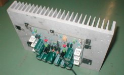
Here's another project I'm currently working on... It's a preliminary PCB stuffed with everything absolutely necessary to get the beast running. Frequency compensation is not yet satisfactory, I'm working on that. You can see my mockup-heatsink (which has seen many many amplifiers on it in the past years - I sand-blasted it for the photo, it was even more ugly (uglier?!) before). Two complementary pairs are still missing, but there are lots of cheapish capacitors, even tantalum caps in the DC servo, all of which will be replaced. I messed up one tapped hole, so one of the driver transistors will have to stay away a bit from the board. The design is very close to a commercial unit, lets see who finds out first ")
Attachments
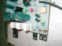
This way of mouting the transistors allows for an easier single-sided PCB layout (paralleling devices without using bridges on component side). It is also easier to repair the amp, as you don't need access to the solder side of the PCB to change power devices. BD139/BD140 will have to be replaced by 2SA1507/2SC3902 as their voltage rating is right at the limit.
Attachments
Very pretty. Love the heatsink.
> I sand-blasted it for the photo
Rough sand-blast surfaces may give poor thermal conduction. Grease is not as good as smooth metal-to-metal contact. I can't see the actual surface condition, but if you are stressing the transistors you might need to smooth the surface for best heat transfer. If you have been trained with a file, a smooth file can make a very smooth surface (or a very bad one if you are a clumsy worker). An electric (or hand) sander with Fine and Extra-Fine grit sandpaper might be better than coarse sand-blasting. A stainless-steel spoon, rubbed HARD over the transistor contact area, would peen-down the high-points and be better than a sand-blast surface.
Rough sand-blast surfaces may give poor thermal conduction. Grease is not as good as smooth metal-to-metal contact.
Don't worry, for now I used tons of thermal grease and the transistors stay cool. It's only a mock-up after all. For the final product, I will sandblast the fins and simply mill the back afterwards.
Re: Inspiration
How did you know?
I see, that you was inspirated by machines made by Accuphase
How did you know?

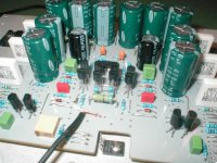
Input, driver and output stage have separate supplies. This is needed, as the PSRR of a CFB input stage is horrible. Additionally, the opamp for the DC servo has its own +/- 15V supply. I first experimented with capacitance multipliers, but I found a simple R-C low pass works best. That's why I have so many caps. And component count is not that low for a 100W mono board. Including output devices, last time I counted I got 27 transistors Compare that to an Aleph!
BTW, I'll be building three stereo amplifiers of this type together with a friend who'll be making a carbon fiber case
Compare that to an Aleph!BTW, I'll be building three stereo amplifiers of this type together with a friend who'll be making a carbon fiber case
Please understand that I cannot post the schematics as I received them under the condition of not posting them in the public. I already moved away from the original a bit (the PCB layout is mine) and probably will change some more things after experimenting, but I gave my promise about that.
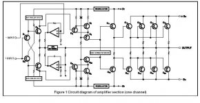
I guess most of you can figure out the circuit from the principle schematic below (taken from Accuphase P-370 product literature). Another very similar design is the Elektor Giant 2000 (or whatever it was called in the English issue).
I will update the thread with new pictures when work progresses, and I intend the focus to be more on the mechanical part of the project. There are some interesting things to come
Attachments
Blitz, just a short update. From an electronic point of view, there was no progress in the project since my last post, as I was very busy. However, I will have some spare time in March and April and I hope to finish this project. I do have a prototype case and heatsinks now.
Next week I'll rework the PCB. I was not happy with the grounding scheme although I didn't have any issues (when running only one channel from a bench PSU, that is). Also, I was not happy with some of the signal tracks. It seems to be a good idea to make a preliminary PCB and have a look at it some weeks later. Sometimes you see some very obvious way of improving things after a pause. With the prototype case at hand, it turned out the PCB can grow a bit bigger which makes life easier.
Stay tuned for some updates (and pictures) this month.
A fully discrete CFB balanced-in / balanced-out preamp will follow
- Status
- This old topic is closed. If you want to reopen this topic, contact a moderator using the "Report Post" button.
- Home
- Amplifiers
- Solid State
- Prototyping a 100W CFB amp...