This thread is continued from 'What is the Gainclone Exactly?'
Ultra Low Cost Amplifier design, here is my first proposal...
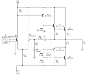
Power is 50W in 8 Ohms, 100W in 4 Ohms, 5 - 100.000 Hz.
It is a fairly conventional amplification stage, followed by a industrial MOSFET output (extremely rugged). It can be tweaked and scaled to larger output power with ease....
The values around T5 may have to be experimented with a little.
It should build for less than 10$ including a PCB. (Which i will not be making or selling .. anyone else can do that if they want).
I encourage anyone with ideas for ultra low cost amplifiers to post them here, and let's discuss some solutions.
You can see an enhanced image here: www.lcaudio.dk/ulcamp1.gif
All the best from Lars Clausen
Ultra Low Cost Amplifier design, here is my first proposal...
Power is 50W in 8 Ohms, 100W in 4 Ohms, 5 - 100.000 Hz.
It is a fairly conventional amplification stage, followed by a industrial MOSFET output (extremely rugged). It can be tweaked and scaled to larger output power with ease....
The values around T5 may have to be experimented with a little.
It should build for less than 10$ including a PCB. (Which i will not be making or selling .. anyone else can do that if they want).
I encourage anyone with ideas for ultra low cost amplifiers to post them here, and let's discuss some solutions.
You can see an enhanced image here: www.lcaudio.dk/ulcamp1.gif
All the best from Lars Clausen
Attachments
Interestng, some questions though: Why have you so high-ohmish feedback?
Why do you choose to have so little gain in the input stage? Isn't it a little bit better to have lower emitter resistance values?
Isn't it smarter to have a mosfet like BS170 for bias? I know that bias circuitry can be tricky but this was just a thought. With a BJT you can get too much mV/degC. I see that you have a zener also so maybe this is enough.
T8 is connected very unusual, never seen before but looks smart from distortion point of view.
How necessary are R1 and R2 in a single pair configuration?
Otherwise looks like a AKSA or Holton deluxe.
Why do you choose to have so little gain in the input stage? Isn't it a little bit better to have lower emitter resistance values?
Isn't it smarter to have a mosfet like BS170 for bias? I know that bias circuitry can be tricky but this was just a thought. With a BJT you can get too much mV/degC. I see that you have a zener also so maybe this is enough.
T8 is connected very unusual, never seen before but looks smart from distortion point of view.
How necessary are R1 and R2 in a single pair configuration?
Otherwise
looks like a AKSA or Holton deluxe.jam: Thanks for your suggestions, i will try to find a current diode at a low price.
chris: The 10$ is of course only for the amplifier circuit, not the power supply and transformer or enclosure. I think this amp can be assembled on a PCB sized 2 by 3 inches. A photo board here would cost a couple of $ (4 by 6 inches) in an electronics shop.
chris: The 10$ is of course only for the amplifier circuit, not the power supply and transformer or enclosure. I think this amp can be assembled on a PCB sized 2 by 3 inches. A photo board here would cost a couple of $ (4 by 6 inches) in an electronics shop.
The Aleph X group buy indicates that lowest you could go with large qty order is $4-5 per board. It is still equal to the price of a chip. And when you use 5 additional parts to complete the circuit, I don't see any justification in choosing discreet route for better performance.
Aleph amp can be regarded as a well implemented and simplified discreet design, actually a benchmark, however I can't say it is superior to a well implemented chip amp. Ask the guys who listened to sexy gear on a table")
Aleph amp can be regarded as a well implemented and simplified discreet design, actually a benchmark, however I can't say it is superior to a well implemented chip amp. Ask the guys who listened to sexy gear on a table
Peranders: The high ohmish feedback is to partly balance the high input impedance 100k, and that one is intended to keep down the value of the 100nF cap in series with the input.
So it is still cheap to get a good quality cap.
High emitter values in the input stage is to keep open loop gain low ( = good sound ).
BIAS circuit, you are right, this stage may require a little fine adjustment, maybe some changes can also improve the design.
R1 and R2 may be unnessescary, depending on how good a thermal coupling you can make. I included them just to be extra sure it will work every time.


NO IT DOESN'T
"Otherwise looks like a AKSA"
I have an ASKA 55 in my amp collection and it is quite different. It is also an excellent sounding amp which is the result of much more than just the basic topology. I doubt you ever seen the schematic since Hugh keeps tries very hard to keep it of the hands of "entrepreneurs" and I haven't seen something similar on your website. Of course I know you would never copy a design into which so much effort was expended in getting it to something far beyond the ordinary.
Setting aside the audio merits of the design presented, in my experience (limited, but it is what it is) the path to "low-cost" doesn't have a lot to do with the amplifier PCB. If you buy only what you need, etch your own PCBs, stick to a BJT output section and avoid exotic components as well as non-exotic NTE -- then the cost differential between a minimalist design and some of the higher component count designs (of Self, Slone and others) is still just pocket change.
The big cost drivers are the enclosure, the heatsinks, the transformer, connectors and filter caps. If you can attack these with a combination of ingenuity, scrounging and a disdain for visual aesthetics, the cost of the completed unit can be driven quite low without making too many compromises on the amp circuitry itself. This is asserted with the understanding it is relative to a given power level.
Thus, I think one might as well just choose the amplifier circuit that best meets one'' audio goals and which is consistent with skill and experience. Where cost is a concern - look to the other areas.
The VBE of T12 (0,65V) limits the voltage over R12, which comes from the current drawn on the collector of T6. If the IC of T6 attempts to go up, the Voltage over R12 goes up, and with it VBE of T12. This subsequently tells T12 to draw more current (away from) the IB of T6, so it's IC falls back down.
On B of T6 you will end up having a temperature compensated voltage with respect to +45V, so the same VB is reused to fuel B of T11. T11 will now track the current drawn by T6, thermally balancing the whole circuit.
This setup is actually a classic amplifier used by a great deal of amplifiers from the late 1980's and 1990's. I have added a few features to it, the buffered Gain Stage, and also a frequency split feedback circuit, so high frequencies are fed back from a short path, (with low time delay) while the lower frequencies where a higher damping factor is eesential, is drawn from the output.
This makes the amplifier better sounding, and more stable to capacitive loads, for the cost of just 2 cheap components.
The latter method can be adapted to work in almost any conventional amplifier circuit. And have the same beneficial effects.
Sam you are absolutely right. The cost of the circuit will often drown in the cost of enclosure, transformer etc.
But i still think it is interesting to have a discussion like this to maybe establish how low can you go with the price of parts, and yet have a good sound, better than the average buy-and-forget amplifier.
As you also say, for somebody who is a little creative, the whole amplifier can be made for almost nothing. Let's hear your ideas out there, also for ultra low cost enclosures etc.
Hi Lars Clausen,
I agree that a discussion with priority on low-cost instead of Hi-end performance can be very refresing. So I'll give it my 2 cents.. or a little less actually.
In your design I can't realy identify the cost-lowering features. The parts count isn't ultra low, nor are the output device particular cheap (or am I wrong here?). It looks to me as a pretty good quality amplifier design, not particular low-cost.
I was planning to submit my own circuit, but it actually is a circuit of Rod Elliot: a version of 'El Cheapo'.. much like:
link: http://sound.westhost.com/project12.htm go to figure 1
but then with a Long-tailed input.
How about that for a cheap amp?
Regards,
Thijs
I'll make a drawring.....
I think this should be our barebone, low-cost, no features but still good functional amplifier to start from... features as MOSFET outputstage, BTJ-bias, buffered Diff-pair etc etc can be added.. but this is it... as sinmple and low-cost but still functional as can get..
I'm sure you won't agree... so let's hear it
Regards,
Thijs
I'm sure you won't agree... so let's hear it
Regards,
Thijs
Attachments
Making a PCB will put a strain on the budget but there is an alternative construction method that is in many ways superior to a PCB.
Layout the components on an un-etched piece of copper-clad board that will form a ground-plane. Cut a strip of board about 5mm wide and cut this into smaller squares that are then super-glued to the ground-plane to form connection nodes for the components. Signal transistors can be glued to the ground-plane which can also double as a heatsink driver transistors.
This type of construction is far more robust than either a PCB or stripboard making component addition and substitution very easy. Once the layout is finished an application of conformal coating keeps the whole thing bright and shiny.
Regarding a low cost amplifer design, how about a hybrid: op-amp front-end with a discrete output stage. Plenty of scope for experimentation and potentially cheaper and better than a single chip amp. The low supply voltage of most op-amps will limit output power but 20-30Wrms should be attainable without adding extra complexity
Richard C
I know this method, it is very nice, but takes some time.
Also there is the MIR method. I saw a film about the last 12 months of the MIR space staion, and they showed some circuit boards from the main control. It consisted of blank boards (could be almost any isolating material) with small holes, where the component wires were stuck trough, and soldered directly to the other component wires. No copper layer at all.
With a bit of layout planning that could work as well, especially if you can drill in something good looking like transparant polycarbonate, and add blue LED's to light the whole glass board.
Just a fun idea!
Regarding the opamp based low cost amp, you could bridge it, use +/- 22V opamps, and still get around 70 W in 8 Ohms.
I think Burr Brown has some and also the NE5532 is 22V. I think though you will have a hard time reaching real high sound quality with the 22V opamps, as they tend to be slow compared to some current feedback opamps working up to 18V rails. But then with good opamps, your budget could be running away ...
Hi,
HA.. that MIR-methode... alot of stuff at the my former job at the university is build that way.. That stuff still works and was build in a day... while nowaday equipment doesn't seems half as reliable and take months to design, get th parts, get the PCB manufactured and everything put together... ooooh well... maybe I'm just old fashioned..
Regards,
Thijs
- Status
- This old topic is closed. If you want to reopen this topic, contact a moderator using the "Report Post" button.
- Home
- Amplifiers
- Solid State
- Ultra Low Cost Amp Design