Do we have a circuit for this amp ?
The differential amp transistors will be the first "pair" with the emitters connected (or closely connected) together. Those metal tabbed driver types would be my suspects but none of this is helping is it")
Be methodical, and it should take very little time to pin the fault down. Ultimately anything could be causing the problem but in practice it will be one of the "usual" suspects. Old preset pots can go intermittent too, not just the wiper but the rivets that secure the leadouts to the carbon track.
Here we are, service manual
Sony TA-3200F | Owners Manual, Service Manual, Schematics, Free Download | HiFi Engine
It will be the more recent of the 2 as mine has the protection board included on the amp board and not separate .
Strange thing, when I was checking all those carbon resistors R139 Left Channel and R219 Right Channel both read 0 resistance. How is that possible? should be 4.7
Thanks. I found a copy
Any resistors that read different in circuit to the marked value need to be confirmed OK by isolating one end. That normally applies to higher values though. Low value ones usually read correct in circuit so in this case I would guess you might have your meter on a range that can't resolve really low values. You need a "low ohms" range. And the amp must be OFF when measuring resistors in circuit.
Any resistors that read different in circuit to the marked value need to be confirmed OK by isolating one end. That normally applies to higher values though. Low value ones usually read correct in circuit so in this case I would guess you might have your meter on a range that can't resolve really low values. You need a "low ohms" range. And the amp must be OFF when measuring resistors in circuit.
Input diff pair transistors are the usual culprit.
Try swapping these transistors from channel to channel.
While you are at it, inspect these transistors for black legs....this is a usual sure sign of noisy transistors.
Regards, Dan.
THere are a number of the small resistors on the board with blackish legs including thee diff 's.
I hear you Mooly.Lots of old parts have black legs.
Stick to a plan for fault finding. Two minutes to swap those transistors around.
1. Swap around the suggested transistors. If that works on to...
2. Tans swapped out for lyrics
3. replace those carbon resistors.
Just a note on the tants when I measure the top lead I get 0v and .042v on the bottom lead. Is the 0v lead the neg? I measure .051v on the right channel tant FYI.
Is then the top lead 0v my negative lead.
That's it
I'd probably put the carbon comps behind the transistor (the one I don't like the look of)
Measure across the tant to determine polarity. If there is essentially zero volts anyway it can be confusing reading from ground to each end.
What's its reference number on the circuit ?
I'll be back shortly......
That's it
I'd probably put the carbon comps behind the transistor (the one I don't like the look of)
Measure across the tant to determine polarity. If there is essentially zero volts anyway it can be confusing reading from ground to each end.
What's its reference number on the circuit ?
I'll be back shortly......
C102 LC and C202 RC - A bit confused by the instructions. I see no polarity on the schematic. DO I measure across the leads with power on?
The polarity is in the symbol. The tiny bit (toward the transistor) is positive. You could use a 4.7uf 16 or 25 volt electro as a good replacement here.
If you measure the voltage (which has to be done with it on) then be careful. One slip could cause damage. The voltage across the cap should tally with the polarity but in these applications where there is so little DC voltage anyway across the cap it might conceivably be reverse biased by a few millivolts. Worth checking, and fitting any cap to comply with what is actually measured.
If you measure the voltage (which has to be done with it on) then be careful. One slip could cause damage. The voltage across the cap should tally with the polarity but in these applications where there is so little DC voltage anyway across the cap it might conceivably be reverse biased by a few millivolts. Worth checking, and fitting any cap to comply with what is actually measured.
The polarity is in the symbol. The tiny bit (toward the transistor) is positive. You could use a 4.7uf 16 or 25 volt electro as a good replacement here.
If you measure the voltage (which has to be done with it on) then be careful. One slip could cause damage. The voltage across the cap should tally with the polarity but in these applications where there is so little DC voltage anyway across the cap it might conceivably be reverse biased by a few millivolts. Worth checking, and fitting any cap to comply with what is actually measured.
Great Mooly, got it on the caps.
Have you changed the tant ?
I wouldn't randomly swap any more transistors yet.
OK, here's what I would.
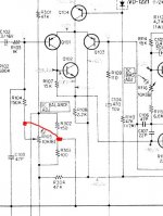
1) Carefully tap and perhaps tweak R105 (the DC balance pot) as it could be intermittent. Does the crackling appear as you tap/touch the pot. Its a moments job to reset the offset back to 0.00 volts.
2) Do you see the small caps, C106 and C107 that go to Q106, They would be next on my list to look at. Are they ceramic disc types ?
Edit... and C103 at the input.
I wouldn't randomly swap any more transistors yet.
OK, here's what I would.
1) Carefully tap and perhaps tweak R105 (the DC balance pot) as it could be intermittent. Does the crackling appear as you tap/touch the pot. Its a moments job to reset the offset back to 0.00 volts.
2) Do you see the small caps, C106 and C107 that go to Q106, They would be next on my list to look at. Are they ceramic disc types ?
Edit... and C103 at the input.
Mooly, I had swapped Q104 before your last post and had power on for 30 minutes or so and dead silent. Could that be Perhaps a re solder is all that was needed. Seems a little suspicious to me. Any how she is working fine.
I have an order into a local supplier to replace the tants and yes, ceramics as well as the carbons. You are right those are small ceramics.
I'm keeping my fingers crossed things stay silent. I'll keep you posted.
I do want thank you for all your help and sticking with me on this.
Clive
Perhaps a re solder is all that was needed. Seems a little suspicious to me. Any how she is working fine. I have an order into a local supplier to replace the tants and yes, ceramics as well as the carbons. You are right those are small ceramics.
I'm keeping my fingers crossed things stay silent. I'll keep you posted.
I do want thank you for all your help and sticking with me on this.
Clive
See post #14 here
http://www.diyaudio.com/forums/soli...315-repair-troubleshooting-2.html#post3396541
Gajanan Phadte
http://www.diyaudio.com/forums/soli...315-repair-troubleshooting-2.html#post3396541
Gajanan Phadte
Well that's great news as you seem to be on to the problem area.
Much more probable is that the heat from the iron has temporarily "fixed" the faulty device so to be on the safe side I would definitely replace Q104 and I think also the double diode D101 as that could be the culprit too.
(with a DC coupled amp its just not worth taking risks for the speakers sake so play safe and replace any suspect items)
Q104 and the diode form a constant current source. The transistor can be replaced with something like the 2N5401 (different pin configuration so beware) and the diode replaced with two series connected 1N4148 or 1n914 types. I would do the same on both channels for completeness.
Attachments
Well that's great news as you seem to be on to the problem area.
Much more probable is that the heat from the iron has temporarily "fixed" the faulty device so to be on the safe side I would definitely replace Q104 and I think also the double diode D101 as that could be the culprit too.
(with a DC coupled amp its just not worth taking risks for the speakers sake so play safe and replace any suspect items)
Q104 and the diode form a constant current source. The transistor can be replaced with something like the 2N5401 (different pin configuration so beware) and the diode replaced with two series connected 1N4148 or 1n914 types. I would do the same on both channels for completeness.
Not so fast, later after a cool down, noise. Frustrating. I started what you suggested Mooly and tapped R105. Tapping did not produce anything but when I
fiddled with the contact it made a similar noise. When I did the same procedure on the R channel no noise. Thought I would swap them around.
If R105 needs replacing the nearest thing I could find is this
3352T-1-100LF Bourns | Mouser
The pins are still a little to narrow as I need about 13mm width but would need to bend the pins.
Yes I'm up late or early
If the noise returned on the same channel after swapping Q104 then it could still be the diode that's faulty... possibly. Heat from a soldering iron often alters faulty parts.
You could swap the presets although it might be better in the first instance to rotate them rapidly to and fro (maybe with drop of WD40 to clean the track and wiper... which some might not approve of) and see if the fault has gone.
If you replace the presets then never bend the leads such that any force is applied to where the pin is bonded to the track. Better to solder short leads on to it or if the board allows, redrill new holes in the PCB. Or better still when you are certain of a fix, replace the pot with two fixed resistors.
You could swap the presets although it might be better in the first instance to rotate them rapidly to and fro (maybe with drop of WD40 to clean the track and wiper... which some might not approve of
) and see if the fault has gone.If you replace the presets then never bend the leads such that any force is applied to where the pin is bonded to the track. Better to solder short leads on to it or if the board allows, redrill new holes in the PCB. Or better still when you are certain of a fix, replace the pot with two fixed resistors.
If the noise returned on the same channel after swapping Q104 then it could still be the diode that's faulty... possibly. Heat from a soldering iron often alters faulty parts.
You could swap the presets although it might be better in the first instance to rotate them rapidly to and fro (maybe with drop of WD40 to clean the track and wiper... which some might not approve of
If you replace the presets then never bend the leads such that any force is applied to where the pin is bonded to the track. Better to solder short leads on to it or if the board allows, redrill new holes in the PCB. Or better still when you are certain of a fix, replace the pot with two fixed resistors.
I did rotate rapidly the pot rapidly and a generous squirt of Deoxit. No effect.
Not sure I understand your last comment "don't alter the DC bias adjust preset (just in case you were wondering) by that method".
I did rotate rapidly the pot rapidly and a generous squirt of Deoxit. No effect.
Not sure I understand your last comment "don't alter the DC bias adjust preset (just in case you were wondering) by that method".
Swinging the DC offset by a few 10's or 100's of millivolts is one thing, swinging the quiescent current quite another. If that pot was cleaned up in a similar way you would have to do it with the amp OFF and then reset the pot to give minimum current initially and then readjust as per the manual.
If you have doubts over the preset then you could remove the pot completely and connect the centre wiper pin to the junction of R302 and R303. That would run it without the pot. There would be a small DC offset error (for safety measure the offset before connecting speakers, anything under 300mv would be OK as a test) but it would prove the pot good or bad.
So it sounds at the moment like the next step is to replace the diode.
- Status
- This old topic is closed. If you want to reopen this topic, contact a moderator using the "Report Post" button.
- Home
- Amplifiers
- Solid State
- Sony TA3200f Issue